


128-7767
13 of 19
13
2 Pin Blue Connector : Programming Switch
Route the gray and black wires in the 2 pin connector from the previously installed programming switch to the control
module and plug it into the mating blue connector on the side of the module.
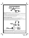
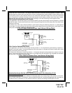
2 Pin White Auxiliary Output Connector : Low Current Trunk Release Output (1Blue Wire Loaded)
This wire pulses to ground via an independent RF channel from the keychain transmitter. This is a transistor-
ized, low current output and should only be used to drive an external relay coil.
WARNING: Connecting this wire to the high current switched output of trunk release circuits will damage the
control module.
Connect this wire to terminal 86 of the AS - 9256 relay (or equivalent 30A automotive relay) and wire the
remaining relay contacts to perform the selected function of this output.
3 Pin Antenna/Receiver Connector: (White Connector)
Plug the previously routed three pin connector from the antenna receiver assemble into the mating connector
of the control module. This connector supplies 12 volts, ground and RF data from the antenna receiver to the
remote start module. Be certain this connector is firmly seated making good contact to the control unit.
2. Programming Tach Rate:
NOTE: All applications require that tach be programmed.
The unit will not operate unless tach is programmed. If an attempt is made to start the vehicle via the remote start without
first programming tach, the unit will flash the parking lights 7 times indicating tach has not been learned and stored.
If the tach rate is not properly programmed to the specific vehicle, the unit may not realize that the vehicle is running
in certain instances and could re-engage the starter motor.
The Remote Car Starter will learn the tach rate of most vehicles single ignition coils, multiple coil packs, and or single
injector. To learn tach;
1. Turn the ignition key to the ON position.
2. Press and release the program switch 3 times.
3. Immediately turn the ignition key OFF.
4. Hold the program switch ON, then start the vehicle using the ignition key.
5. When the unit senses the tach signal, the parking lights will begin to flash.
6. Release the program switch. The parking lights will turn on for 3 seconds to indicate that the tach signal is stored
and the unit is now out of the program mode.
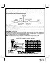
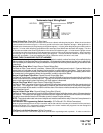
3. Diagnostics:
1. Be sure that programmable feature number #9 is set to the "Diagnostics On" mode.
2. Press and hold the program switch on, then turn the ignition key to the "ON" position.
3. The lights will flash and the number of flashes will indicate the reason for shutdown on the last remote start attempt.
The indications are as follows.
1 Flash 5, 10, 15, or 20, minute run timer expired.
2 Flashes Low or No tach signal received.
3 Flashes Positive input shut down.
4 Flashes Control switch was moved to "Off" position.
5 Flashes RF Shutdown command received.
6 Flashes High RPM signal over speed shut down.
7 Flashes Tach has NOT learned.
8 Flashes Negative input shut down
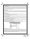
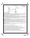
Multi Coil Pack Adapter: (Optional)
The multi coil pack adapter, (P/N 136B1400), is designed for use with vehicles that do not respond to single coil tach
programming. Although the tach resolution of this circuit is designed to interface direct with most vehicles, there may
be an occasion where the following circuit may be required.
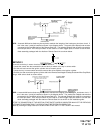
To use the adapter, the Green/Black wires must connect to the negative side of the ignition coil(s).
1. For vehicles utilizing independent coils per cylinder, connect the three Green/Black leads to alternate coils. To