


128-7767
17 of 19
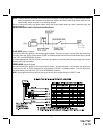
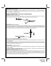
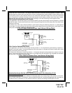
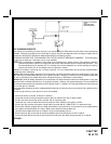
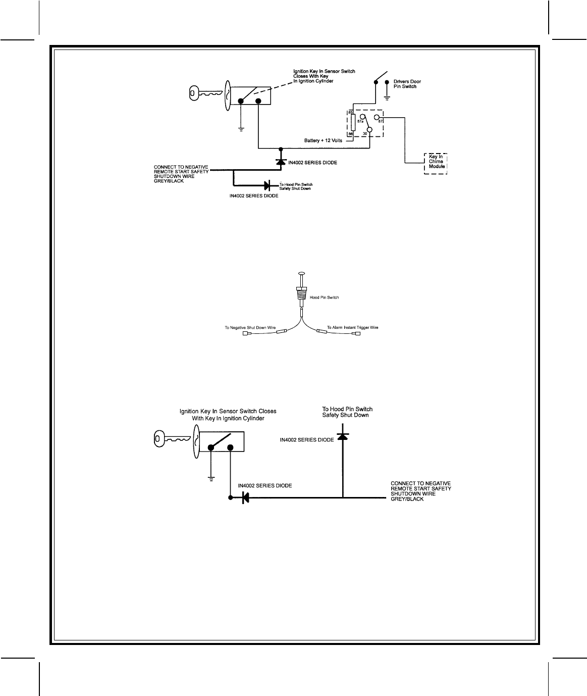
METHOD 2
To connect to the key in sensor circuit as shown for method 2:
A. Locate the control wire that connects the drivers door pin switch to the key in sensor switch.
B. Cut this wire and connect the ignition cylinder side to chassis ground.
C. Locate the key in sensor switch wire that connects the chime module to the ignition cylinder .
D. Cut this wire and connect the ignition cylinder side to the Remote Start Negative Safety Shut down Wire Gray/Black,
using a 4002 series diode as shown above.
NOTE: A second 4002 series diode may be required to maintain the integrity of the hood open, shut down circuit. If
this is the case, it must be installed as shown in the diagram above. The anode (Non Striped) side must be
connected to the Gray/Black wire of the Remote Start Unit. The cathode (Striped) side must be connected to
the hood pin switch. If the hood pin switch is also used for an alarm trigger input, be certain to use the dual
diode assembly packaged with the Audiovox Remote Start Unit as shown in this installation guide.
AFTER THE CONNECTION OF THE NEUTRAL START SAFETY WIRE AS INDICATED IN ANY OF THE PREVIOUS
ALTERNATE CONFIGURATIONS, THIS CIRCUIT MUST BE TESTED FOR OPERATION.
Retest by following the steps outlined in the NEUTRAL START SAFETY TEST shown in this manual.
17
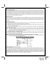
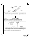
NOTE: A second 4002 series diode may be required to maintain the integrity of the hood open, shut down circuit. If
this is the case, it must be installed as shown in the diagram above. The anode (Non Striped) side must be
connected to the Gray/Black wire of the Remote Start Unit. The cathode (Striped) side must be connected to
the hood pin switch. If the hood pin switch is also used for an alarm trigger input, be certain to use the dual
diode assembly packaged with the Audiovox Remote Start Unit as shown below.