


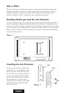
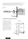
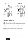
You must be careful to accurately drill the holes or else the screws may not line
up with the holes in your Wall Plate (WP).
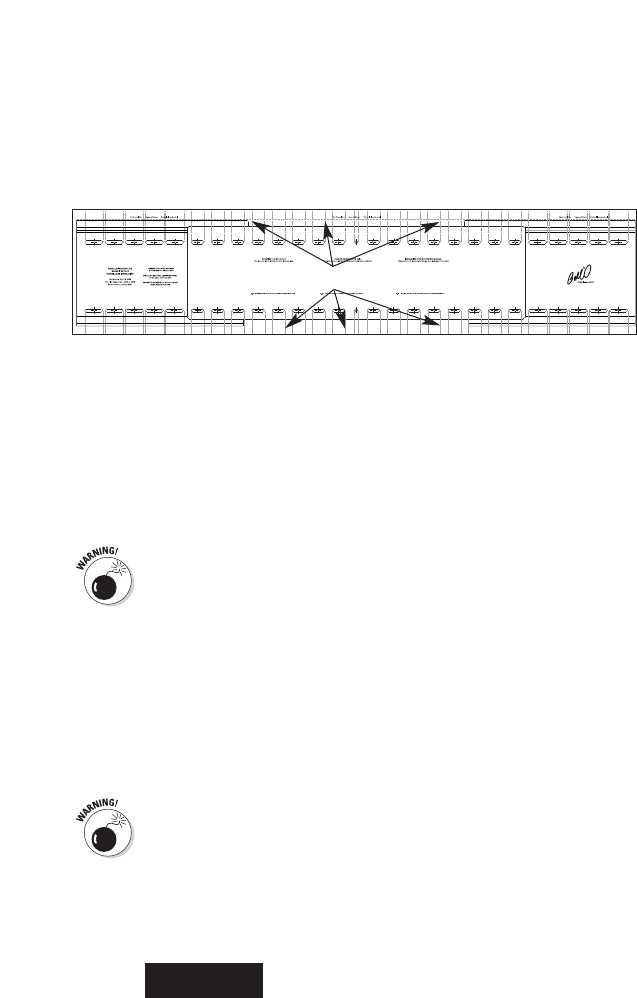
Line up the installation template with your stud markings to ensure the proper location for
your drill holes. After you have the position selected, tape the template in place securely
on the wall with masking tape so that you don’t damage the wall surface. Use a level to
double-check that the screw holes will line up vertically. Drill all holes 2.5" (64mm) deep
using a 5/32" (or 4mm) size drill bit. Follow the directions on the installation template
carefully. The mount is designed to be installed into two studs if the expansion plates are
in the 1st or 2nd hole position as shown on page 11. If the mount is in the third or wider
expansion slot it must be mounted to three studs.
English
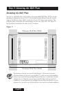
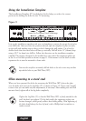
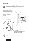
Using the Installation Template
The Installation Template (IT) included in this kit helps you select the correct
positions for drilling the holes for the TV mounting.
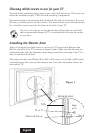
Figure 9
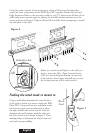
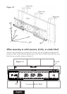
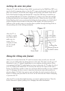
When mounting to a wood stud
When you have prepared the holes for mounting the Wall Plate (WP), place the plate
over the holes and screw in the Lag Bolts (T), as shown in Figure 10.
Leave some “wiggle”
room so that you can make any fine adjustments, if necessary. After making sure the wall
mount is level, tighten all of the lag bolts completely.
Tighten the Lag Bolts (T) so that the Wall Plate (WP) is firmly attached to the
wall, but don’t over-tighten! The lag bolts and/or the supporting surface can
become damaged, which greatly reduces their holding ability. Final tightening of
the bolts should always be done by hand, with a Phillips-head screwdriver or
ratchet wrench.
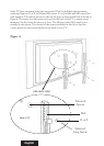
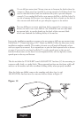
Lines for Locating Stud Markings