


724-746-5500 | blackbox.com
Page 10
724-746-5500 | blackbox.com
Chapter 2: Overview
• 19-inch rackmount brackets
• User manual
2.4 Hardware Description
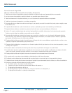
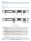
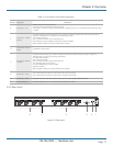
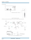
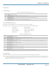
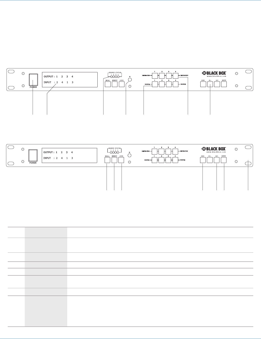
Figures 2-1 and 2-2 show the front panel of the switch, and Figure 2-3 shows its back panel. Tables 2-1 and 2-2 describe the
components.
2.4.1 Front Panel
1 3 2 6 5 4 7
Figure 2-1. Front-panel diagram #1.
9 11 12 13 8 10 14
Figure 2-2. Front-panel diagram #2.
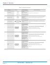
Table 2-1. Front-panel components.
Number Component Description
1 Power Switch
The power switch turns the unit on and off. The LED will light red to indicate that the switch is on and is receiving power. The
switch will remember that last state during a power cycle. When power is removed and restored, the last configuration will be used.
2 Input Status Display Input sources 1 to 4 LEDs light blue to indicate that a video source is present on that input.
3 Output Status Display Each output (destination) channel shows which input (source) is assigned.
4 Destination Select Buttons Separate outputs 1 through 4 select buttons are provided for each destination assignment.
5 Source Select Buttons
Separate inputs 1 through 4 select buttons are provided for each source selection. Source buttons 1 and 2 are used to change EDID
modes when the EDID button is pressed.
6 IR Sensor
The IR sensor receives IR commands from the supplied remote control or third-party emitter.
7 Function Key — ALL
Disables (mute) video on all destinations OR selects the same source to all destinations.
Option 1: Press ALL followed by the OFF button. The display will show “0,” indicating that all destinations have no video selected.
Option 2: Press ALL followed by Source 1 through 4. The display will show the source selected.
Press ENTER and the preset source selection will be assigned to all destinations.