


27
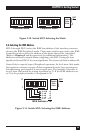
CHAPTER 3: Getting Started
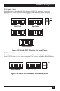
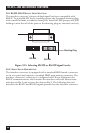
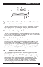
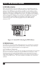
Figure 3-16. Rear View of the Interface Converter’s Serial Connector.
-RxD Receive Data—Input—Pin 2
This pin accepts serial data sent by the RS-232 or RS-422 host. The serial
data is expected with the word length, baud rate, stop bits, and parity
selected by the internal switches. The signal level is low true.
-TxD Transmit Data—Output—Pin 3
This pin transmits serial data to the RS-232 or RS-422 host. The serial data
is sent with the word length, baud rate, stop bits, and parity selected by the
internal switches. The signal level is low true.
CTS Clear To Send—Input—Pin 4
The CTS input is used as a hardware-handshake line to prevent the
interface converter from transmitting serial data when the RS-232 host
is not ready to accept it. When RTS/CTS handshake is selected on the
internal switches, the interface converter will not transmit data out -TxD
while this line is un-asserted (lowered). If the RS-232 host is not capable
of driving this line it can be connected to the Vtest output (Pin 6) of the
interface converter. If X-ON/X-OFF handshake is selected, the CTS line
is not tested to determine if it can transmit data.
RTS Request To Send—Output—Pin 5
The RTS output is used as a hardware handshake line to prevent the
RS-232/RS-422 host from transmitting serial data if the interface converter
is not ready to accept it. When RTS/CTS handshake is selected on the
internal switches, the interface converter will drive the RTS output high
when there are more than 1,000 character locations available in its
internal buffer. If the number of available locations drops to less than
1,000, the interface converter will unassert (lower) this output. If
Xon/Xoff handshake is selected, the RTS line will be permanently
driven active (high).
13 1
25 14
-RXD
-TXD
CTS
RTS
+VTEST
GND
+VTEST
+RXD
+TXD