


31
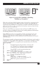
After plugging the power-supply connector into the interface, plug the power
supply into AC line power. Turn the rear-panel power switch ON (the “1”
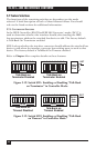
position). All the front-panel indicators should light momentarily while the
interface converter performs an internal ROM and RAM self-check. At the
end of this self-check, all indicators except POWER should turn off.
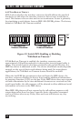
If there is an error in the ROM checksum, all of the LEDs will remain on.
Flashing LEDs indicate a RAM failure. Should such an error occur, turn the
rear-panel switch to the OFF [0] position and retry the above procedure.
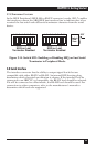
If the front-panel indicators do not flash and the POWER indicator does not
remain lit, there may not be any power supplied to the interface. In this event,
check the AC line and the rear-panel connection of the power supply. If the
problem is unresolved, call your supplier.
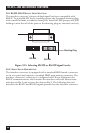
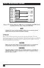
If proper operation is obtained, connect an interface cable to the DB25 port
on the rear of the interface converter. Connect the other end to the host’s
serial port. Except for connecting IEEE bus instruments, the interface
converter is installed and ready to use.
WARNING
The interface converter makes its earth-ground connection through the
serial interface cable. It should only be connected to the IEEE host.
Failure to do so may allow the interface converter to float to a bus-device
test voltage. This could result in damage to the interface, personal injury,
or death.
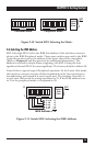
CHAPTER 3: Getting Started