


5
®
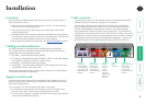
Installation
Locations
Please consider the following important points when planning the location of
the ServSwitch Secure unit:
• Situate the unit close to the host computers to which it will be connected
and also the user console peripherals.
• The unit requires a power supply input, so a nearby spare mains power
outlet will be required.
• As keyboard and mouse switching codes are not possible for security reasons,
the only way to change channels is via the front panel buttons. Therefore, the
unit should be easily accessible from the user’s normal position.
• Please consult the precautions listed within the Safety information section.
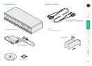
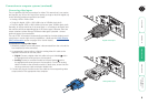
Cabling recommendations
It is vitally important to use good quality shielded cables to minimise the
risk of signal emissions that may be intercepted. Please follow the following
recommendations when specifying cables:
• DVI cables - should be braid and foil shielded.
• VGA cables - should be braid and foil shielded. If DVI-I to VGA style adapters
are used these should be of the fully ‘canned’ variety.
• USB cables - should be braid and foil shielded.
• Audio cables - should be braid shielded with fully shielded connectors (not
unshielded connectors with drain wires).
We strongly recommend that you fit ferrite cores at both ends of every cable to
further assist with emission suppression.
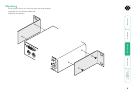
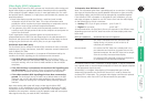
Tamper-evident seals
Given the high security nature of most installations that incorporate this unit, it
may be a policy of your organisation to fit tamper-evident labels across certain
seals and/or chassis screws.
The unit assists in the use of tamper-evident seals in two ways:
• All chassis retaining screws are countersunk so that their heads are flush
with the outer covers, making it easy to apply seals across them.
• The main cover is coated in a special matt finish that is particularly suited for
contact with self-adhesive strip seals.
SECT 3
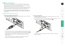
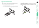
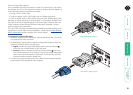
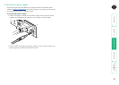
Links overview
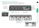
The rear panel of the unit is well marked, however, the diagram below offers
additional clarity on how best to arrange your connections.
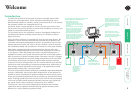
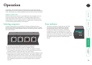
You may have noticed that the indicators on the front panel use different
colors to represent the various channels. This is done to provide quick and
effective visual feedback to the operator. Channel 1 has a green indicator
and is traditionally used for the lowest security connection. The final channel,
numbered 2 on the two port version and 4 of the four port version, uses a red
indicator and is usually connected to the highest security connection. These are
configuration conventions only and are offered as a suggestion - there are no
technical differences in the operational specifications of the four channels.
4 3
5V
2.0A
USERCONSOLE
I
NDOOR
US
EO
NL
Y
12
Channel 1
(green indicator)
Usually used
for connection
to the lowest
security computer/
network.
Channel 4
(red indicator)
Usually used
for connection
to the highest
security computer/
network.
Console
connections
Connect directly
to the operator’s
keyboard, mouse,
video display and
speakers.
Channel 3
(amber
indicator)
On two
channel
models,
this port is
labeled 2 and
uses a red
indicator.
Channel 2
(blue
indicator)