


Page 9
724-746-5500 | blackbox.com
Chapter 2: Overview
• (1) 3-ft. (0.9-m) VGA cable
• RS-232 Control Software
• (1) IR remote control (includes batteries)
• (1) power supply
• This user’s manual
2.4 Hardware Description
2.4.1 Front Panel
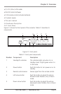
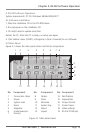
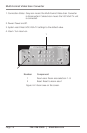
Figure 2-1 shows the front panel of the converter. Table 2-1 describes its
components.
1 6 7 8 9
2 3 4 5
Figure 2-1. Front panel.
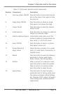
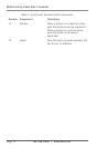
Table 2-1. Front panel components.
Number Component Description
1 Standby/On indicator This indicator lights red when it is in
standby mode. It lights green when it is
in ON mode.
2 Power button Push this button to turn power on or to
standby.
3 Remote control sensor Senses signal from the remote control.
4 Left arrow button Push the button to adjust the picture
leftward under Position, Pan, or Zoom
mode.
5 Down arrow button Push the button to adjust the picture
downward under Position, Pan, or Zoom
mode.