


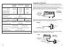
Installation Step Two
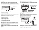
The camera mounts using a single gang “J” box. Run a line of Cat 5
wire from the camera to the channel injector and connect wires as
shown.
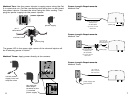
Attach Cat 5 wire to camera following color coding.
note:
When using quad wire connect
wires only to pins 1, 2, 5 and 6.
Leave the resistor in place
at pins 3 and 4.
Programming a New Channel
Valid channels are 14 thru 64 for UHF and 65 thru 125 for CATV
Channels 95-99 are not available. Channels 21 thru 62 are for Pal.
Channel Spacing:
Skip at least one number between the new channel and the closest
existing UHF/CATV channel.
(example 14 and 16: OK 14 and 15: Unacceptable)
Error Indication:
If an error occurs or an incorrect channel is entered, the LED will
flash quickly for one second and return to previous settings.
Cable HRC and IRC considerations:
Most cable services use IRC frequency assignments. This is the
default for the 9500 series. However, if the cable services uses HRC
or the TV appears to search for the “created channel”, program the
channel injector for HRC.
For HRC enter 98. Reset to IRC by entering 99.
Entries 98 and 99 are for setting HRC or IRC only. They will not
change the channel number.
With programming complete, test each TV in the system to see that it is
receiving the new channel.
4
9
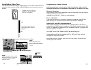
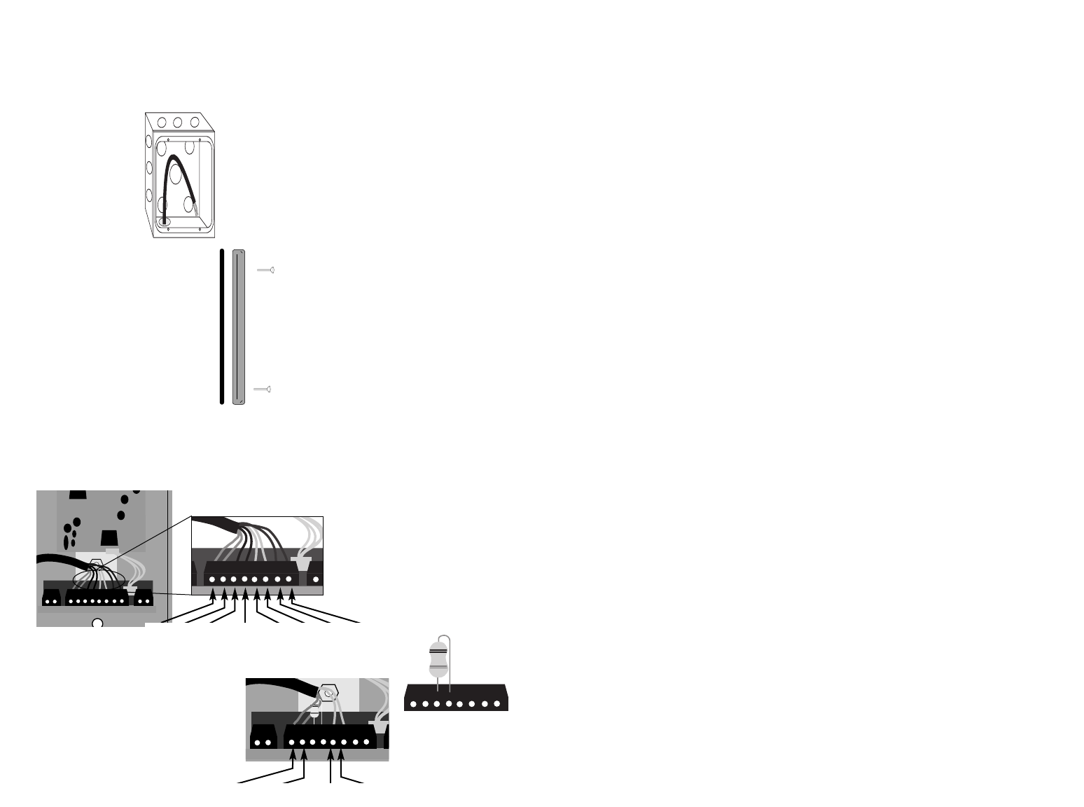
note:
When using Cat 5 wire
remove the default resistor
that is in pins 3 and 4 of the
camera
prepare the Cat 5 wires by
stripping 1” of outer sheath
and 1/8” of insulation
insert the 6-32 screws into
frame and bottom holes of
gang box
frame
gasket
pin 1 2 3 4 5 6 7 8
Default
resistor
Green
pin 1
Red
2
Black
5
Yellow
6
Bl/W Blue Org/W Orange Gr/W Green Br/W Brown