6 7
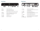
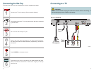
Front Panel
1 Power Turns the set-top on and off
2 Arrows Indicates an active cable modem link
3 Record Press to enable an instant recording.
Note:
® illuminates to indicate a recording in progress
4 Display Displays the selected channel number and time of day
5 IR Sensor Receives the infrared signal from the remote control.
The sensor is behind the front panel
6 Vol-, Vol+ Adjusts volume
7 CH-, CH+ Scrolls through channels
8 USB Port Reserved for future use
Back Panel
1 AC In Connects to a power receptacle
2 Cable In Connects to the coaxial cable that delivers the signal from
your service provider
3 TV Out Connects to RF input of TV
4 Ethernet Connects to Ethernet-equipped device
5 L/R Connects to left/right audio inputs of TV or other device
6 V Connects to composite video input of TV
7 Y PB PR Connects to component video input of TV
8 L/R Connects to left/right audio inputs of TV or other device
9 SPDIF Connects to digital audio input of a TV or other device
10 SIM Card Reader Reserved for future use
RECORD
–
+
VOL CH
8
T14093
31 2 54 76
AC IN
100-240V
50-60Hz 32W
SIM CardSPDIFRL
TV OutCable In
Ethernet
VRL
Pb PrY
T14094
1 2 3 645 987 10


