


CMRCI-BSS/SB
5
Display
8 CMRCI-BSS/SB
3
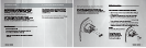
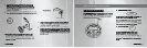
” (mm)
Diameter
Hole
Mounting Bracket
VOL
BAND
DISC
POWER
SOURCE
MUTE
VOL
Break Lines
4. Insert the remote control panel into the opening. Make sure
that the gasket behind the remote control panel face seats
completely against the mounting surface.
5. Position the bracket onto the rear of the remote control panel,
sliding the two threaded studs on the rear of the panel through
the two holes in the mounting bracket (as shown below). Tight-
en the 7mm hex nuts onto the bracket, again ensuring that the
gasket seals tightly to the front of the mounting surface. Avoid
pinching the cable.
Using the Remote Control Panel
Using the Remote Control Panel
The CMRCI BSS/SB remote control allows the user to control
the Clarion CMD4 or M455 AM/FM/CD Player from a remote
location, even if the source unit is mounted out of sight in a
compartment or in a different area.
USING THE REMOTE CONTROL PANEL
To turn the unit on, press this button momentarily. To
turn the unit off, press and hold for 1 second.
When the CMD4 is already on, press momen tarily to
switch between the CD and the AM/FM tuner.
This button also accesses the optional Sirius Satellite
Radio receiver and the optional CD Changer.
The
[BAND/DISC]
button:
The
[POWER/SOURCE]
button:
In Radio and Sirius Satellite Radio modes
:
Switches among AM, FM, and optional Sirius
Satellite Radio bands, and selects among the
various memory registers (FM1, FM2, SR1, SR2, etc.)
In CD Changer mode
: selects the next available CD.
In CD mode
: begins playback from the beginning of
the CD.
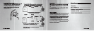
1. Determine the mounting location is a fl at surface with suf-
fi cient rear clearance (2.5”) and access.
Ensure that the
installation can be successfully completed before con-
tinuing!
If the cable is not long enough, a 24ʼ extension is
available - P/N M101RXC
.
2. The remote control panel requires a 2” (51mm) diameter round
hole. Cut the hole and insert the remote control panel as shown.
3. The mounting bracket is scored with “break linesʼ to allow
use with panels of different thicknesses. Determine if the
bracket needs to be shortened, and remove the appropriate
number of breakaway segments using a pair of pliers. Each
segment is 1/4” long.