28 TB741P/TB742P/TB743W
English
Installation and Wire
connection manual
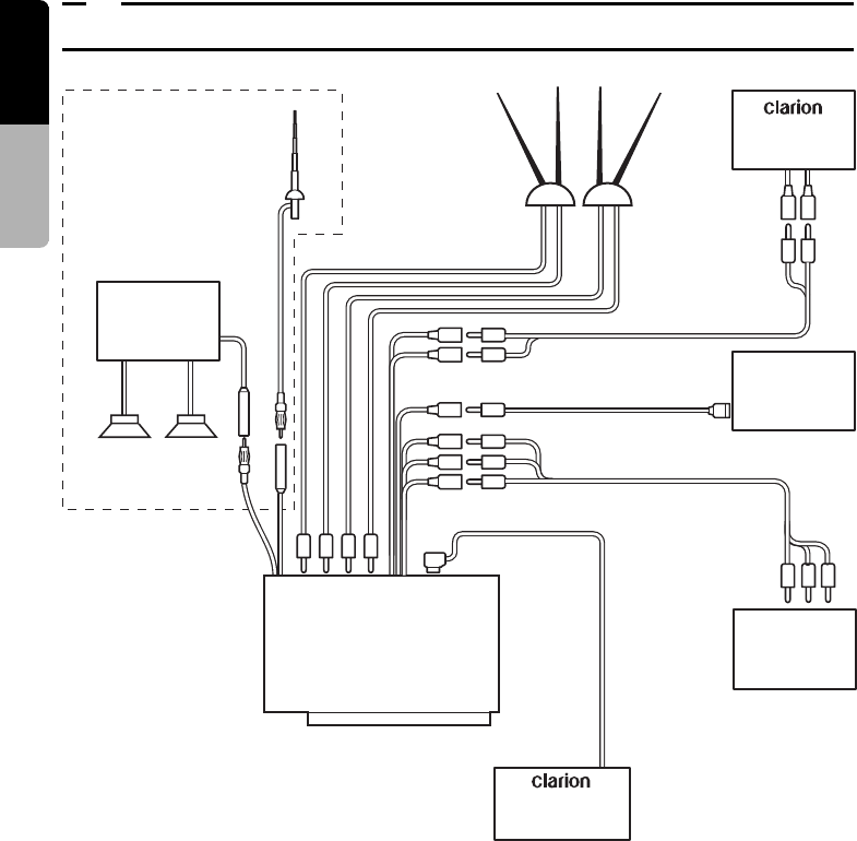
9. SAMPLE SYSTEMS
Radio antenna
CCD Camera
(sold separately) or
External device
(VTR2)
4-system TV diversity
antenna
(sold separately)
Connected to system
expansion terminal
Connected to video output
terminal (RCA pin jack)
REAR MONITOR
(sold separately)
Center unit
with AUX input
Main unit
TB741P/TB742P/TB743W
Speakers
Clarion products
or Car stereo with
FM Tuner (sold
sepatately)
Connected to video/audio input terminals
(RCA pin jacks) (sold separately)
External device
(VTR1)
(sold separately)
(sold separately)
TB741P/TB742P only
Connected to audio
output terminals
(RCA pin jacks)
Notes:
• For details on the connecting terminals, refer to
the section on wire connections (page 26).
• A External device can be connected to the system
expansion terminal using the CCA-389
conversion cable.


