


16
CIRCUIT OPERATION
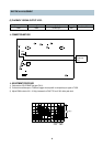
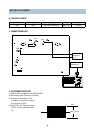
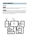
1. VIDEO PART
1-1) EE MODE
Video Signal which is output from RL902 is input to pin 37 of IC301 through OSD IC. It is amplified 6dB by AGC, then it is
output to pin 34. This output signal is output to Video Jack through RL902 of RELAY IC.
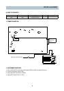
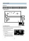
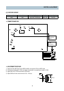
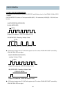
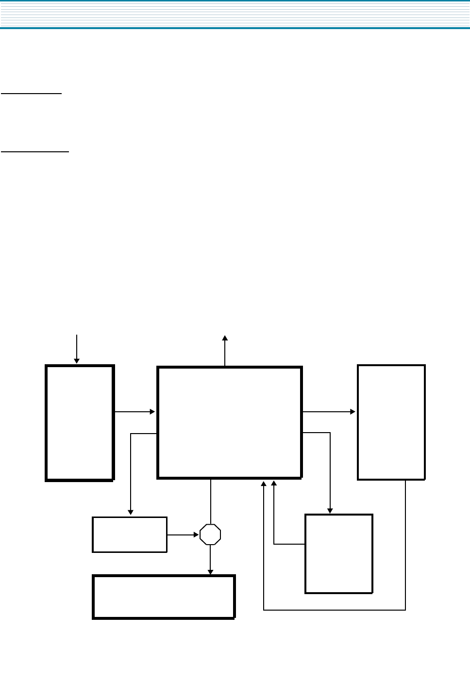
1-2) REC MODE
The signal which is input to pin 37 of IC301 is output to pin 3 through IC internal AGC AMP. If this output signal has burst,
it is input to X303 then it separates color signal. If it has not burst, it will pass Y-Emphasis circuit. Each signal is input to
pin 4 then passes 3.5M LPF. Luminance signal is output from pin 40 after FM modulator through MAIN-Emphasis and
color signal is output from pin 15 after low-converted. Each signal is input to pin 12 of IC401 through REC-EQ, then it is
recorded on the tape through HEAD after passing out MIX AMP.
VIDEO IN
VIDEO OUT
V.IN
IC001
OSD IC
IC301
VIDEO IC
REC EQ
IC401 HEAD AMP
Y-EMPA
CIRCUIT
X303
Y/C
COMB
WITH
BURST
REC C
REC Y