


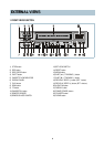
6
ELECTRICAL ADJUSTMENT
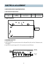
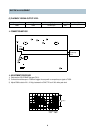
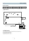
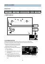
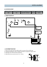
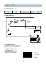
1. SERVO/SYSCON CIRCUIT ADJUSTMENT METHOD
v
VIDEO HEAD SWITCHING POSITION
v
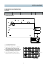
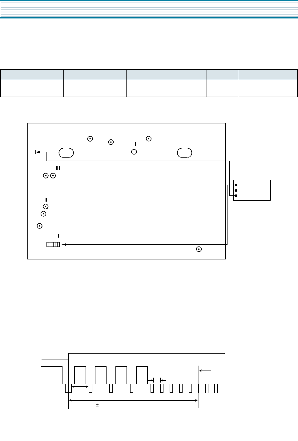
CONNECTION METHOD
v
ADJUSTMENT PROCEDURE
1) Play back the test tape.
2) Set the oscilloscope in the chop mode connect the CH1 to SW pulse(PT501 (r)PIN), the CH2 to TJ396(video out) with
CH1 triggering.
3) Adjust R595 for the positive trigger until 6.5
±
0.5H cycle before the vertical SYNC pulse.
Adjustment Part Checking Point Measuring Equipment Mode Test Tape
R595
TJ396
PT501 PIN3
OSCILLOSCOPE Play DN-1 (Color Bar)
TJ396
CH-1
Oscilloscope
CH-2
PT501
R595
CH1
SW PULSE
(PT501 3PIN)
VIDEO OUT
(TJ396)
Vertical SYNC Signal
1H
6.5H 0.5H
Trigger Position