


1
CIRCUIT DESCRIPTION
Video
1. Outline
This video circuit uses a LA71598SM Super A/V 1 chip IC made by SANYO which includes luminance and color pro
cessor, CCD and PREAMP.
This IC has 100 pin, but only 79 pin(10~74 pin and 81~94 pin) are related to Video circuit among them.
2.Video circuit
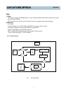
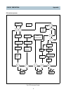
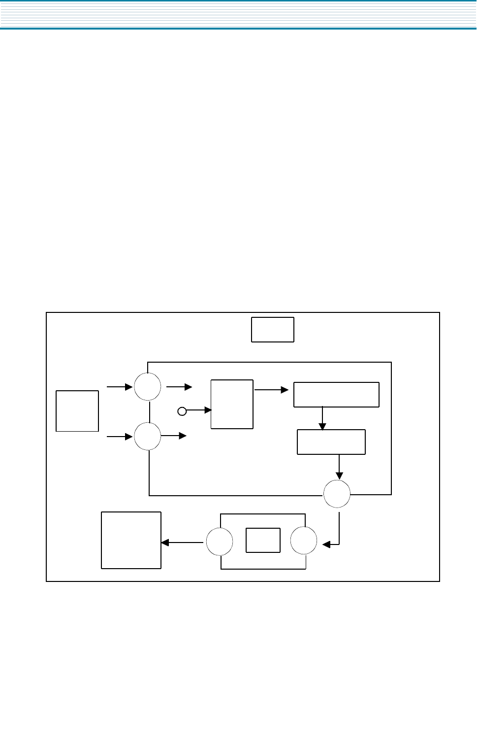
A. EE mode
1.0Vp-p video signal out of SCART JACK or CHROMA IC is input to pin 38,34, of ICY01.
One of them is selected, and input to AGC AMP(sync and peak AGC).
Output from AGC AMP is input to QV/QH insert circuit.
After it is amplified 6dB through Video Amp, 2.0Vp-p signal is output to pin 29.
Finally it is output through pin 17 of I501(TDA8841)
EE mode process
Fig . 1 EE mode process
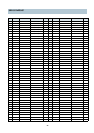
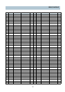
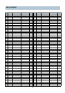
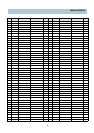
Appendix
38
Video
in
34
29
AGC
AMP
QV/QH INSERT
VIDEO AMP
ICY01
17
13
I501
SCART
JACK
OUT