


2
CIRCUIT DESCRIPTION
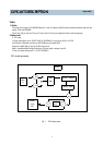
B. REC mode
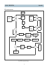
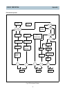
a) Luminance Signal Processing
The signal is to pin 38,34 of ICY01, and one is selected to input to AGC AMP.
This input signal performs sync AGC and peak AGC.
And then , it is input to the 6dB divider where its level is educed to 0.5V.
LPF and 1H Delay separates luminance signal from output signal of the divider.
The separated luminance signal is passed through pin 21, and it is input to pin 20.
The level is clamped in clamp circuit which fixes sync tip to a specific DC level in order to prevent
Frequency drift while video signal is converted to FM signal.
The edge of the signal is emphasized by Detail Enhancer.
The emphasized signal is supplied to Non-Linear Emphasis circuit to improve S/N ratio.
Non-Linear Emphasis circuit adjusts amount of emphasis in high frequency in LP mode,
which means that amount of emphasis is dependent on the input level, for instance, the lower input level, the
large amount of emphasis.
Main emphasis emphasizes the high frequency of the adjusted signal again.
White/Dark clip is conducted in order to prevent the luminance signal from undershooting and overshooting
which are occurred during the above emphasize process.
The luminance signal modulated by FM modulator is passed through REC-EQ, modulated Y signal is mixed
with the down converted color signal.
It is supplied to AGC Amp of Pre-Amp section and then supplied to video head through Pin 84 in SP mode or
LP mode.
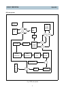
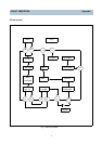
b) Color Signal Process
The video signal input from pin 38,34 of ICY01 is passed through AGC AMP and BPF.
A color signal separated by 4.43MHz BPF.
This signal is supplied to Comb Filter, and separated color signal.
Then the signal goes to ACC section which automatically controls color burs level.
After Burst Emphasis boots burst signal 6dB, 4.43MHz carrier frequency is input to Main converter and mixed
with 5.06MHz carrier frequency from sub-converter.
In the long run, the output is 5.06MHz
6
4.43MHz.
The down-converted 627KHz color signal, the difference between two frequencies, is passed through color
LPF.
The output signal is mixed with modulated Y-FM signal and supplied to AGC part.
It is supplied to the head through pin 84 in SP mode or LP mode.
Appendix