


9
CIRCUIT DESCRIPTION
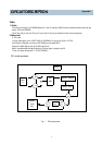
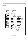
3 Explanation by Mode
A. Mute Control ( pin 10 )
B. Explanation by mode
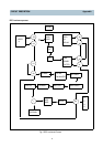
a) EE mode ( Rear line IN )
The line input signal divided by RU29 and RU30 is input to pin 76 of IC, and output to pin 96 through ALC circuit and
Line Amp.
At same time and the signal is passed through voltage divided circuit (RU08 and RU09) and CU06, input to REC Amp.
ALC point is fixed on 4dBm by RU06 and RU07, and ALC time can be adjusted by RU31 and CU23.
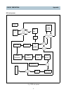
b) PB mode
The signal from audio head input to pin 4 through frequency equalizer circuit composed of RR18 and CU15, This input
signal is output to pin through EQ Amp.
It is input to pin 100 through buffer, R221 and finally output to pin 96 through Line Amp.
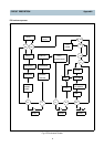
C) REC mode
The Audio input signal is passed Line Amp, and the level is reduced by divided circuit composed of RU08 and RU09.
This signal is input to REC Amp through de-emphasis circuit composed of RU10 and CU07.
The audio signal from pin 7 of REC Amp is mixed with Bias signal, 70KHz and recorded in A/C Head.
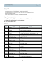
Control Port
Mode
Function
Mute Line SW
H Mute
Except for Mute
Open
Close
L
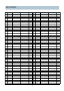
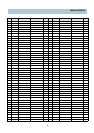
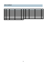
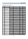
Appendix