


7
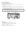
DISASSEMBLY
• Disassemble in order of the arrow of the fi gure of following fl ow.
• In the case of the re-assembling, assemble it in order of the reverse of the following fl ow.
• In the case of the re-assembling, observe "attention of assembling" it.
• If wire bundles are untied or moved to perform adjustment or parts replacement etc., be sure to rearrange them neatly
as they were originally bundled or placed afterward.
Otherwise, incorrect arrangement can be a cause of noise generation.
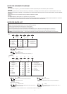
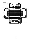
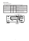
About the photos used for descriptions in the DISASSEMBLY" section.
• The direction from which the photographs used herein were photographed is indicated at "Direction of photograph: ***"
at the left of the respective photographs.
• Refer to the table below for a description of the direction in which the photos were taken.
• Photographs for which no direction is indicated were taken from above the product.
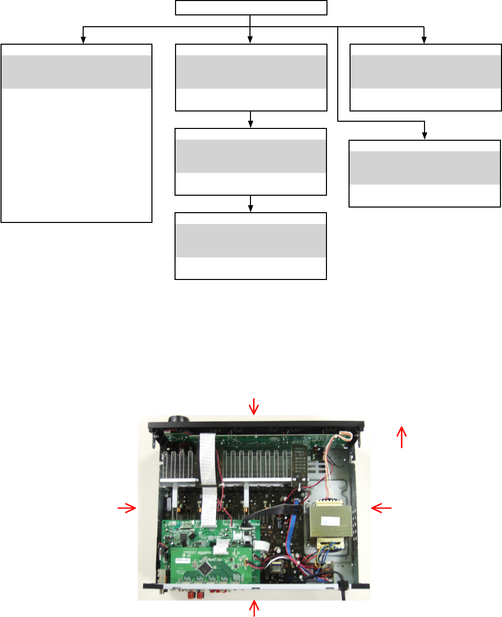
The viewpoint of each photograph
(Photografy direction)
View from above
Front side
Direction of photograph: B
Direction of photograph: D
Direction of photograph: C
Direction of photograph: A
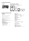
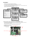
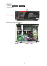
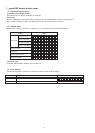
FRONT PANEL ASSY
Refer to "DISASSEMBLY
1. FRONT PANEL ASSY"
and "EXPLODED VIEW"
AUX UNIT
(Ref. No. of EXPLODED VIEW : C1)
PHONE UNIT
(Ref. No. of EXPLODED VIEW : C2)
VOLUME UNIT
(Ref. No. of EXPLODED VIEW : C3)
HEADPHONE UNIT
(Ref. No. of EXPLODED VIEW : C8)
POWER UNIT
(Ref. No. of EXPLODED VIEW : C9)
FRONT UNIT
(Ref. No. of EXPLODED VIEW : C10)
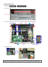
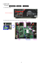
HDMI UNIT
Refer to "DISASSEMBLY
2. HDMI UNIT"
and "EXPLODED VIEW"
HDMI UNIT
(Ref. No. of EXPLODED VIEW : C7)
INPUT UNIT
Refer to "DISASSEMBLY
3. INPUT UNIT"
and "EXPLODED VIEW"
INPUT UNIT
(Ref. No. of EXPLODED VIEW : C6)
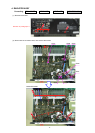
RADIATOR ASSY
Refer to "DISASSEMBLY
4. RADIATOR ASSY"
and "EXPLODED VIEW"
MAIN UNIT
(Ref. No. of EXPLODED VIEW : C5)
TOP COVER
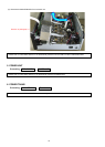
POWER UNIT
Refer to "DISASSEMBLY
5. POWER UNIT"
and "EXPLODED VIEW"
REGULATOT UNIT
(Ref. No. of EXPLODED VIEW : C13)
POWER TRANS
Refer to "DISASSEMBLY
6. POWER TRANS "
and "EXPLODED VIEW"
POWER TRANS
(Ref. No. of EXPLODED VIEW : C14)