


83
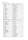
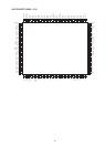
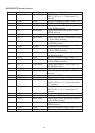
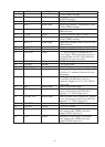
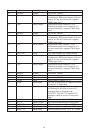
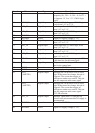
Location Mnemonic Type Description
N = 1, 2, 3, or 4. Set to 128 × sampling
frequency (fs), 256 × fs, 384 × fs, or 512 ×
fs. Supports 1.8 V to 3.3 V CMOS logic
levels.
69 SCLK_IN Digital Input I2S Audio Clock. Supports CMOS logic
levels from 1.8 V to 3.3 V.
70 AP5_IN Digital Input Audio Input Port 5. CMOS logic levels
from 1.8 V to 3.3 V.
71 AP4_IN Digital Input Audio Input Port 4. CMOS logic levels
from 1.8 V to 3.3 V.
72 DGNDIO Ground Ground for DVDDIO
73 DVDDIO Power Digital I/O supply voltage (3.3 V)
74 AP3_IN Digital Input Audio Input Port 3. CMOS logic levels
from 1.8 V to 3.3 V.
75 AP2_IN Digital Input Audio Input Port 2. CMOS logic levels
from 1.8 V to 3.3 V.
76 AP1_IN Digital Input Audio Input Port 1. CMOS logic levels
from 1.8 V to 3.3 V.
77 AP0_IN Digital Input Audio Input Port 0. CMOS logic levels
from 1.8 V to 3.3 V.
78 SDATA Digital I/O I2C port serial data input/output pin. SDA
is the data line for the control port.
79 SCL Digital Input I2C port serial clock input. SCL is the clock
line for the control port.
80 DGND Ground Ground for DVDD
81 DVDD Power Digital supply voltage (1.8 V)
82 INT1
(AMUTE1)
Digital Output Interrupt pin, can be active low or active
high. When status bits change, this pin is
triggered. The events that trigger an
interrupt are under user control. This pin
can also output an audio mute signal
83 INT2
(AMUTE2)
Digital Output Interrupt pin, can be active low or active
high. When status bits change, this pin is
triggered. The events that trigger an
interrupt are under user control. This pin
can also output an audio mute signal.
I2C LSB selection.
84 INT_TX Digital Output Interrupt. Open drain. A 2 kΩ pull-up
resistor to the microcontroller I/O supply is
recommended.
85 DGNDIO Ground Ground for DVDDIO
86 DVDDIO Power Digital I/O supply voltage (3.3 V)