


Page 1
Page 2
1
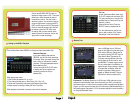
Connect
4 Channel DVR
Use only the power adapters supplied with the Q-See unit. We recommend
Plugging the DVR and Cameras into a Transient Voltage Surge Protector
(UL-449 Rating)* 330 or lower clamping voltage, Joule rating 400.
CAUTION:
POWER BUTTON
POWER/ HARD DRIVE LIGHTS
CHANNELS 1-4/ QUAD
REWIND
PAUSE
1
2
3
4
5
DOWN
RIGHT/ SELECT/ EDIT
LEFT/ MENU/ ESCAPE
UP
11
12
13
14
PLAY
FAST FORWARD
STOP
RECORD
PTZ BUTTON
6
7
8
9
10
2 3
FRONT VIEW
REAR VIEW
4 5 6 7 8 9
11
10
12
1
14
13
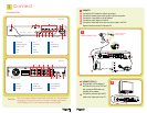
Connect the 60 ft. extension cable to the camera
Connect the female power end of the 60 ft. cable to the splitter
Connect the 4 way splitter to the AC Adapter
Connect the power supply to the DVR
Connect the video feed on the other end of the cable to the DVR
Repeat the same process for Cameras 2-4
Plug the BNC to RCA adapter to
the Video Out port on the DVR and
then connect an RCA cable (not
included) to the adapter
Connect the other end of the RCA
cable to the Video Input on the TV
CAMERA CONNECTIONS
1 CONNECT
1
2
2 CONNECT TO A TV
A
B
A
C
B
D
E
4 C ha nn el D ig it al Vid eo R ec or de r
PWR HDD
CH1 CH2 CH3 CH4 QUAD
REW PA USE PLAY FWD STOP REC
PTZ
CH1
CH3 CH4 AIN3
AIN1 AIN2
LAN
AIN4
VIDEO
OUTPUT
AUDIO
OUTPUT
CH2
VIDEO INPUT
VIDEO OUTPUT
AUDIO INPUT
USB PORT (USB MOUSE)
RS-485/ SENSOR/ ALARM
POWER PORT
AUDIO OUTPUT
ETHERNET PORT
USB PORT (USB DEVICE)
4
5
6
1
2
3
7
8
9
1
32 4
5
6 8 9
7
CH1
CH3 CH4 AIN3
AIN1 AIN2
LAN
AIN4
VIDEO
OUTPUT
AUDIO
OUTPUT
CH2
CH1
CH3 CH4
CH2
Yellow: Video Out
Black: Power In
CH1
CH3 CH4 AIN3
AIN1 AIN2
LAN
AIN4
VIDEO
OUTPUT
AUDIO
OUTPUT
CH2
A
E
D
B
C
A
B