


12
© 2001 Directed Electronics, Inc.
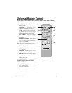
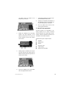
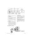
1. Audio out - Use these outputs for stereo
audio signal to IR wireless headphones or an
FM modulator. The audio zones correspond
to the same monitor zones so any time a
source is changed the audio will follow.
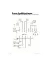
2. Monitor zones - These eight-pin DIN plugs
are audio and video outputs. Using the
VDC100, they plug directly into the
Directed Video line of overhead and head-
rest monitors. They include stereo audio
signal, video signal, IR signal, and data
signal for ESP/ESP2 communication.
3. ESP/ESP2 Port - This three-pin port is for
adding the ESP/ESP2 security system with
two-way communication. It allows infor-
mation to flow between the security sys-
tem and the MCB 1000. User-programma-
ble features of the ESP/ESP2 systems can
be changed using on screen menus.
Security system violations can be reported
on screen with the name of the violated
zone or sensor displayed.
4. FM Modulator control - This plug is used
for controlling power to the RFM100 FM
modulator. The MCB1000 will turn the RFM
100 power on/off by the ignition switch or
the system operator can turn the FM mod-
ulator on/off by remote control.
5. Infrared input - This is a 3.5mm pin plug
for a remote IR eye. The optional IR 100
Infrared remote receiver can be added to
the system to allow full control from any
location in the vehicle.
6. Extended menu switch - Set this switch
to the ON position and a special Setup
Menu for the installer will appear on
screen with the rest of the menus. It is
designed allow the installer to customize
the system hardware operation, program
the Directed ESP/ESP2 security system
trigger names, and name the AV zones for
the on-screen display. Set the switch to
the OFF position and the Setup Menu no
longer appears with the on-screen menus.
Refer to the On-screen Programming guide
for further information.
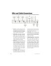
Wire and Cable Connections