


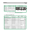
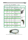
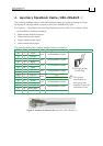
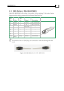
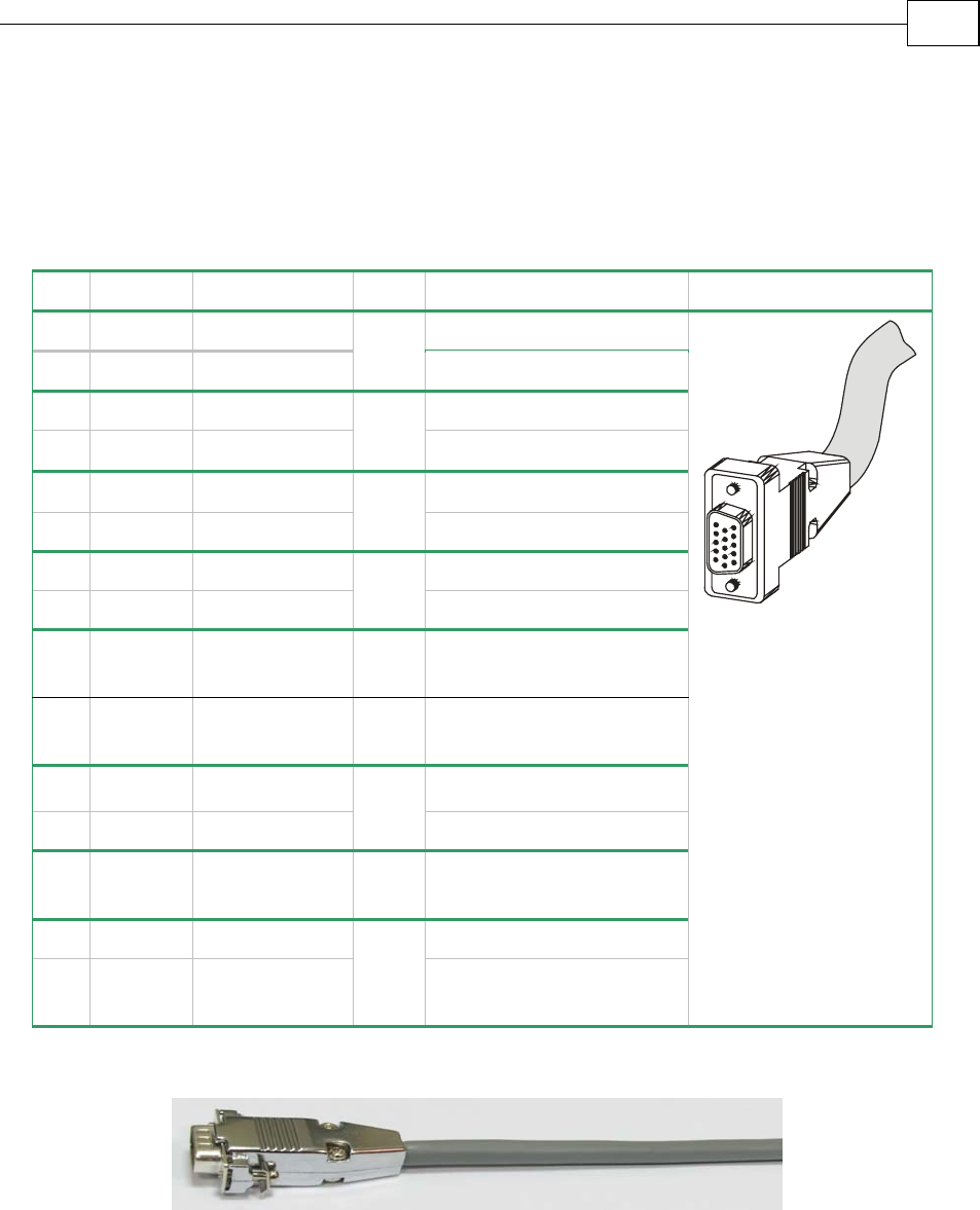
5. General I/O J1 (CBL-CELIO1-5)
The digital input cable is a 24-AWG shielded cable. It is connected using an 15-pin Hi-
Density D-sub socket.
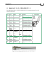
Pin Color Signal Pair Function
Pin Position
1
Orange
IN1 Programmable input 1
2
Cyan
IN2
pair
Programmable input 2
3
Purple
IN3 Programmable input 3
8 Black IN8
pair
Programmable input 8
4
Gray
OUT2 Programmable output 2
5 Pink OUT3
pair
Programmable output 3
6 Blue IN4 Programmable input 4
7 Red IN7
pair
Programmable input 7
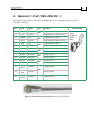
9
White/
Yellow
INRET
General input return
10
White/
Red
OUTRET2-3
Programmable output
return 2 & 3
11 Yellow OUT4 Programmable output 4
13 Green OUT5
pair
Programmable output 5
12
White/
Black
OUTRET4-5
Programmable output
return 4 & 5
14 Brown OUT1 Programmable output 1
15 White OUTRET 1
pair
Programmable output
return 1
Figure 5: General Purpose I/O Cable (Part No. CBL-CELIO1-5)
15 Pin
D-sub
Socket
Cello Cable Kits
MAN-CBLKIT-CEL (Ver. 1.0)
8