


© Emerson Power Transmission Manufacturing, L. P. or affiliates 2002. All Rights Reserved.
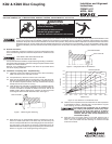
CENTERASSEMBLY
HUB BOLTS
O.D. PILOT
ADAPTER RING
COLLAPSING BOLT
DISC PACK
SPACER
Disconnect all power before adjusting units
3.0 Alignment
Note: Exact values and procedures for aligning equipment are normally
specified by the equipment manufacturers. Good initial alignment to
the minimum possible values will promote optimum machinery per-
formance and eliminate potential operating problems. After securely
tightening the foundation bolts, the hub separation and alignment
should be rechecked and adjusted if necessary.
The coupling alignment should be checked periodically. Even
when a coupling is well aligned at installation, subsequent settling of
foundations, shifting of equipment, etc., may cause the alignment to
deteriorate.
Offset and Angular Alignment
3.1 Reverse dial indication or optical methods of alignment (such as la-
ser) are recommended. A cold alignment and a hot check (with cor-
rections if necessary) are required. The hub flange OD can be used to
mount the alignment equipment. The hub flange OD is machined to
be concentric to the coupling bore and can be used as the reference
diameter.
3.2 The maximum recommended operating misalignment is:
0.10 degrees per disc pack
(0.0035 in/in TIR equivalent parallel offset)
Important: Total misalignment is the combination of equipment par-
allel offset
and angular misalignment.
Note that improving the alignment below these values will promote
optimum machinery performance.
Axial Alignment
3.3 Align the hubs until they are at the correct hub separation. The hub
separation is measured from the two flange faces, not from the pilot
face.
Hub Separation = Center Assembly Length
4.0 Final Assembly
(KD2 and KD20)
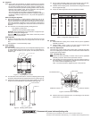
4.1 After correctly installing both hubs, use the separate collapsing screws
to pull the adapter rings toward the center of the pre-assembled cen-
ter section. This is made up of the spacer, two disc packs, and two
adapter rings.
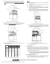
Figure 5. Installing center section.
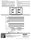
Table 1. Flange Bolt Tightening Torques.
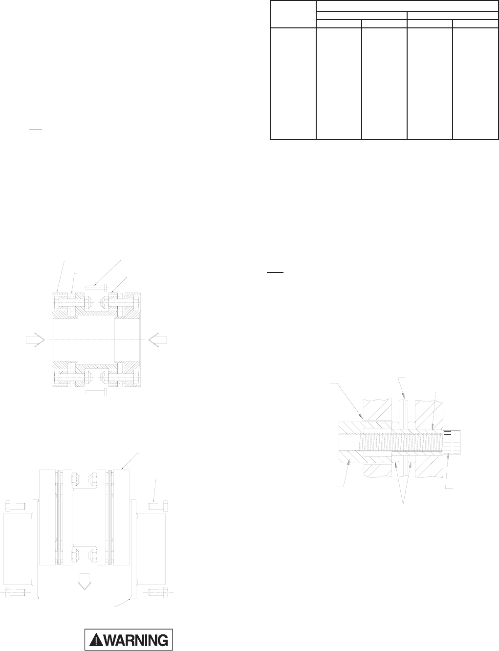
Figure 4. Collapsing center section
Figure 6. Bolt Disc Pack to Adapter.
4.4 Put the center assembly (spacer and rings) between the rigid hubs,
engage the pilot, and install the hub bolts in one hub flange.
4.5 Release all the collapsing bolts, and install the hub flange bolts on the
second rigid hub flange.
4.6 Torque the hub flange bolts to the value specified in Table 1.
4.2 For each side of the center section, insert the collapsing bolts through
the spacer clearance holes into tapped holes in the ring (see Figure 4).
4.3 Tighten them evenly and collapse the disc packs equally, only enough
to allow the center assembly to drop intoplace (see Figure 5).
5.0 Removal
5.1 Disassemble the coupling in the reverse order as per the applicable
assembly procedure.
5.2 KEYED HUBS - Install a puller on the hub using the tapped holes
provided in the hub face. Pull the hub off the shaft.
6.0 Disc Pack Replacement
The terminology used to identify parts and the order of assembly may differ
from one coupling style to another. Follow the instructions which match the
coupling style being installed.
KD2 - For KD20 skip to 6.7
6.1 Remove the center assembly in reverse order as per the applicable
assembly procedure. Remove disc pack bolts and nuts.
6.2 Insert the disc pack removal socket into one of the clearance holes in
the spacer flange or ring (Figure 6). Install the removal cap screw and
turn it until it cannot be tightened any more.
Note: The removal socket is supplied as part of the “parts kit”.
6.3 Remove the tool and repeat step 6.2 on all bushings to free the disc
pack from the ring and spacer.
gnilpuoC
eziS
)deliOylthgiL(euqroTgninethgiT
2DK02DK
bl-tfm-Nbl-tfm-N
301801----
351801----
402,30203040507
452,35203040507
403,30357001011051
453,35357001051002
404,304051002072073
454,354051002072073
405----034085
455----046078
406----046078
507----02110051
508----07410002
509----07410002
CLEARANCE HOLE
DISC PACK
BUSHING
REMOVALSOCKET
WASHER
REMOVALSCREW
The Emerson logo is a trademark and a service mark of Emerson Electric Co.