


© Emerson Power Transmission Manufacturing, L. P. or affiliates 2002. All Rights Reserved.
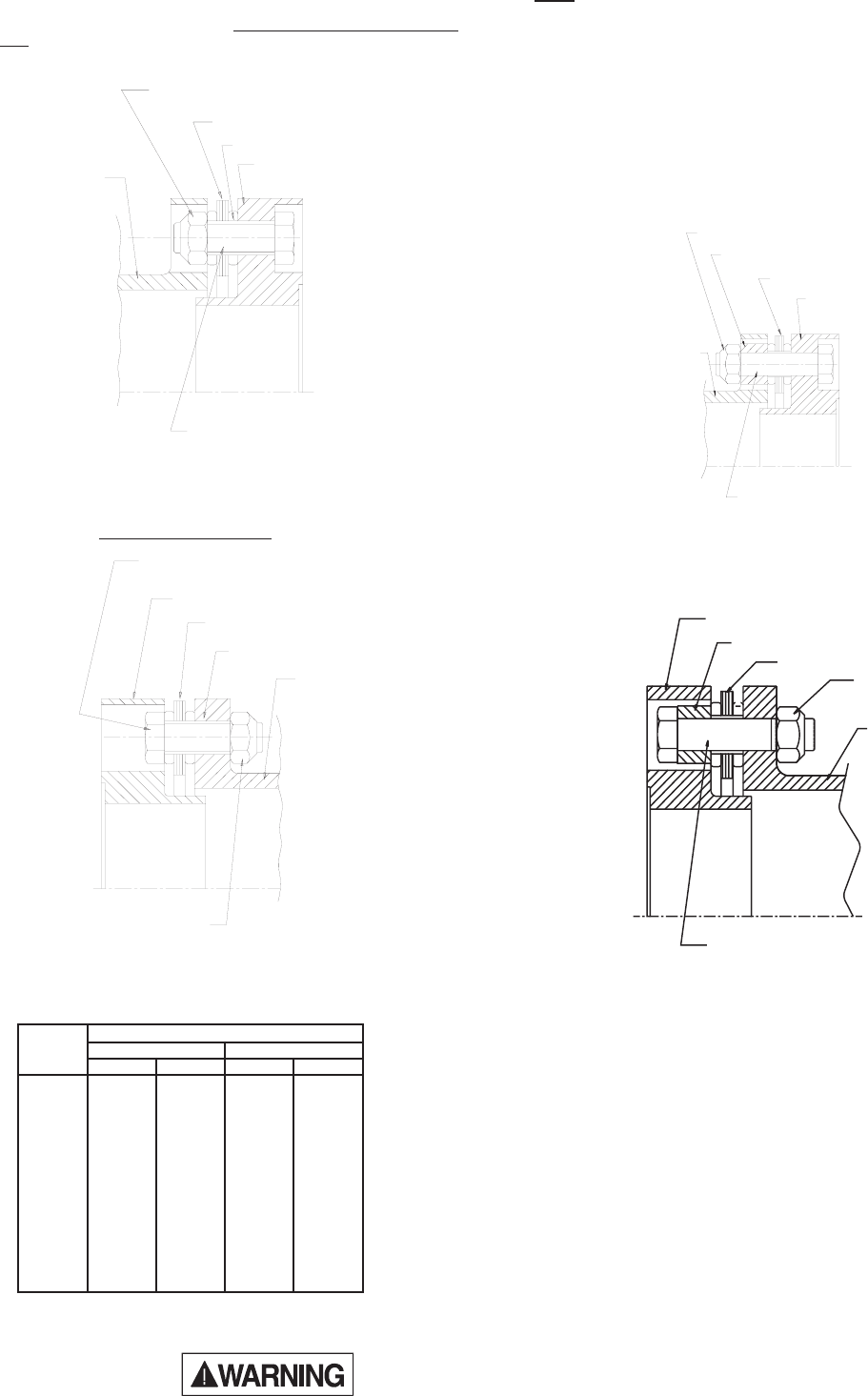
DISC PACK NUT
ADAPTER RING
SPACING WASHER
DISC PACK
DISC PACK BOLT
SPACER
DISK PACK BOLT
ADAPTER RING
DISC PACK
BUSHING
SPACER
DISC PACK NUT
DISK PACK NUT
SPACER
DISK PACK
BUSHING
ADAPTER RING
DISK PACK BOLT
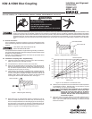
Disconnect all power before adjusting units
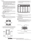
Figure 7. Bolt Disc Pack to Adapter Ring.
6.6 Torque all disc pack fasteners evenly and in successive steps to the
value specified in Table 2.
Table 2. Disc Pack Bolt Tightening Torques.
6.5 Line up the bushings with the spacer reamed holes, lightly tap the
bushings to start them in the holes. Install and tighten 3 disc pack
bolts and nuts
with bolt heads in the ring (see Figure 8).
KD20
6.7 Remove the center assembly in reverse order as per the applicable
assembly procedure.
6.8 Unbolt the adapter ring from the disc pack. Unbolt the disc pack from
the spacer.
6.9 Clean and deburr all of the coupling parts.
6.10 Line up the new disc pack between the adapter ring and the spacer.
Insert the disc pack bolt into the counterbored hole in the adapter
ring, and through the disc pack.
6.11 Make sure that the spacer is properly indexed for the large clear-
ance holes to receive the bolt ends. Place the spacing washer and
disc pack nut on the bolt. Repeat for the other bolts (see Figure 9).
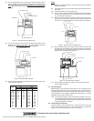
Figure 9. Bolt Disc Pack to Adapter Ring.
6.12 Place a spacing washer over a disc pack bolt. Insert the bolt through
the large hole in the adapter ring and through the disc pack bushing
and reamed hole in the spacer. Place the disc pack nut on the bolt.
Repeat for the other bolts (see Figure 10).
6.13 Torque all disc pack fasteners evenly in successive steps to the
value specified in Table 2.
7.0 Dynamic Balance
Balanced parts will be marked with the letter “B.” The couplings may be
component balanced (hubs and center assembly) with no match marks, or
assembly balanced as a complete coupling with match marks of the hub to
ring connections. If the coupling is supplied with match marks, it must be
assembled with the match marks in line.
Note: For balanced couplings, disconnecting the disc packs from the cen-
ter assemblies disturbs the balance of the coupling. When disc packs
are replaced in balanced couplings, the couplings must be balanced
before placing back in operation.
8.0 Finish Boring and Keyways
Coupling hubs are often furnished with a “rough stock bore.” This rough
bore is not necessarily concentric to other hub diameters. To prepare for
boring, set-up and indicate the hub as shown in Figure 11.
Figure 10. Bolt Disc Pack to Spacer.
6.4 Line up the bushings of the new disc pack with the reamed holes in
the ring, lightly tap on the bushings to start them into the holes. Insert
3 disc pack bolts and nuts with the
bolt heads in the ring counterbore
hole, tighten them evenly to pull the bushing into the ring flange (see
Figure 7).
Figure 8. Bolt Disc Pack to Spacer.
gnilpuoC
eziS
)deliOylthgiL(euqroTgninethgiT
2DK02DK
bl-tfm-Nbl-tfm-N
301801----
3510304----
402,30205075557
452,352570015557
403,303021061511061
453,353091062571042
404,304092093082083
454,354023034082083
405----024075
455----0370001
406----02010041
507----00810542
508----00320013
509----00320013
ADAPTER RING
SPACING WASHER
DISC PACK
DISC PACK NUT
SPACER
DISC PACK BOLT