


© Emerson Power Transmission Manufacturing, L. P. or affiliates 2002. All Rights Reserved.
Important Safety Instructions
Before start-up . . . for reasons of safety and to extend shaft coupling life,
follow these requirements.
1. Coupling guards protect personnel.
ALL COUPLINGS MUST BE COVERED WITH A GUARD AS PER OSHA REQUIREMENTS.
2. Recheck alignment after all foundation bolts and mechanical connections are tightened.
3. Make sure all fasteners are properly installed and tightened.
4. Take the time to double check your work.
5. Only authorized KOP-FLEX replacement parts are to be used.
6. Call KOP-FLEX for any clarification or questions.
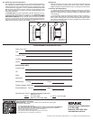
5 YEAR WARRANTY REGISTRATION CARD
Name (Last, First)
Title:
Company Name:
Location:
Phone:
APPLICATION DATA
Coupling Type:
HP:
RPM:
Application:
Shaft Size(s): Driving: Driven:
Distance Between Shaft Ends
Plant Identification Pump # Motor #
Send Warranty Card To: Attention Marketing Department
KOP-FLEX, Inc.
Mail to: P. O. Box 1696 or Fax to: 410-787-8424
Baltimore, MD 21203-1696
9.0 Bore Sizing and Recommended Fit
The finish bore size should be based on the actual measured shaft dimen-
sion, regardless of whether straight or taper shaft. For keyed shafts, a light
interference fit based on a nominal interference rate of 0.0005 inch per inch
of shaft diameter is suggested, or refer to published AGMA standards. Do
not exceed an interference fit of 0.001 inch/inch of shaft diameter. If other
than a light interference fit is desired, consult the published AGMA boring
and keyway standards.
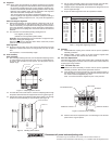
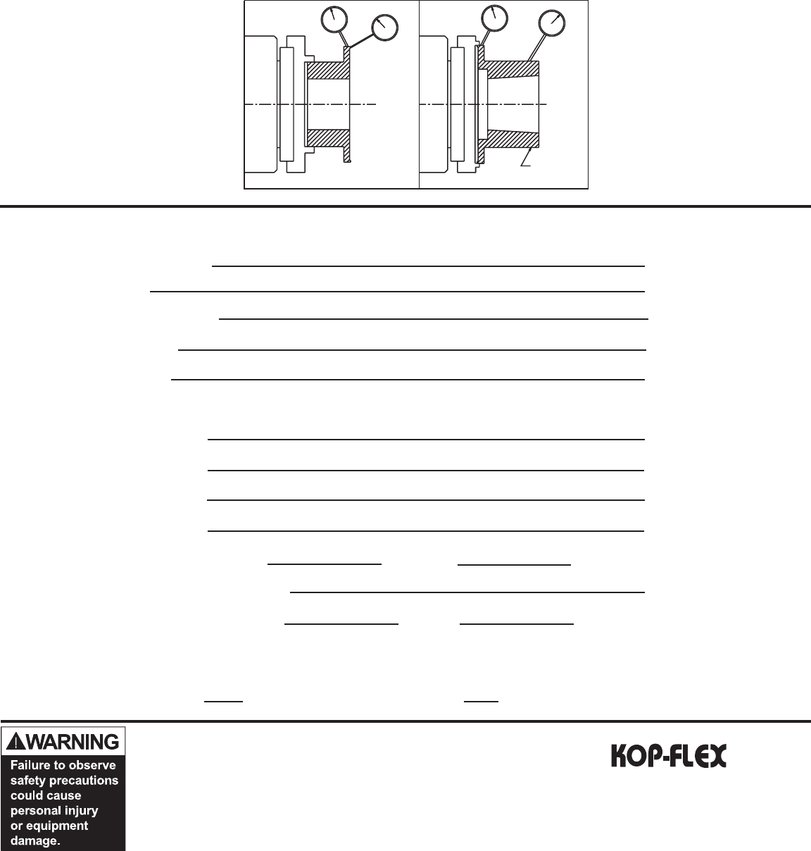
For Straight Bores, the rigid hub diameter should be chucked in the bor-
ing lathe and dial indicated as shown of Figure 11. For Taper Bores, chuck
and indicate as shown on Figure 11. Machine the counterbore and SKIM A
REFERENCE DIAMETER on the hub body. Then chuck the hub as shown
on Figure 12, and indicate using the reference diameter before final boring.
Run-outs should be as near zero as possible. It is essential that the fin-
ished bore be concentric with the two indicating surfaces.
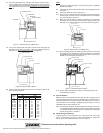
10.0 Keyways
Keyways should be cut to give a tight fit on the sides and slight clearance
over the key. Keyways should not have sharp corners. Refer to published
AGMA standards for specific dimensioning of coupling bores and keyways.
11.0 General Recommendations
11.1 KOP-FLEX KD2 and KD20 disc couplings are designed to operate for
extended periods without the need for lubrication or maintenance. Visual
inspection of the disc packs is sufficient to assess the operational condition
of the coupling.
11.2 All machinery should be monitored to detect unusual or changing vi-
bration levels. KOP-FLEX KD2 and KD20 couplings, under normal condi-
tions, have no wearing parts and will retain their original balance quality.
Any change in vibration levels should be investigated and remedial action
should be taken immediately.
Figure 11
Figure 12
REFERENCE
DIAMETER
Emerson Power Transmission
P. O. Box 1696
Baltimore, MD 21203-1696
www.emerson-ept.com
®