


56 • ARMS Orderguide • rev. 05/30/03 870-03-005
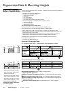
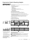
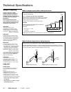
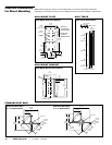
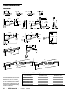
Interface Dimensions
for Direct Mounting
Note: Surface construction varies. It is recommended that you consult the appropriate architectural,
engineering or construction personnel to ensure ARMS are properly mounted to handle the applied loads.
1-1/8"
(29 mm)
1/2"
(12.7 mm)
1-1/4"
(31.8 mm)
2-1/2"
(63.5 mm)
3-1/2"
(89 mm)
1/2"
(12.7 mm)
8-3/8"
(213 mm)
ø.281"
(7.1 mm)
(6 through holes)
#10-24
(10 tap holes)
#8-32
(4 tap holes)
3-3/4"
(95 mm)
Holes used
to attach
Vertical Mount
Outline of
an attached
Vertical Mount
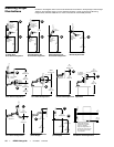
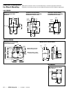
WALL MOUNT PLATE
Wall Mount Plate Hole Pattern
.87" (22 mm)
5" (127 mm)
8"
(203 mm)
4"
(102 mm)
2"
(51 mm)
.5"
(13 mm)
8"
(203 mm)
8"
(203 mm)
1"
(25 mm)
1"
(25 mm)
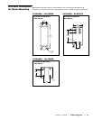
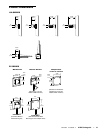
WALL TRACK
Wall Track Hole Pattern
2.5"
(64 mm)
.406"
(10.3 mm)
1"
(25 mm)
7"
(178 mm)
.5"
(13 mm)
8"
(203 mm)
5"
(127 mm)
Center-line
TOP
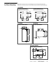
WALL MOUNT BRACKET
Wall Mount Bracket Hole Pattern
Ø .55"
(14 mm)
12.36"
(314 mm)
6.18"
(157 mm)
13.38"
(340 mm)
6.65"
(169 mm)
.87"
(22 mm)
1.38"
(35 mm)
12.36"
(314 mm)
10"
(254 mm)
7.52"
(191 mm)
Center lines
Ø .55"
(14 mm)
Center lines
6.18"
(157 mm)
13.38"
(340 mm)
6.65"
(169 mm)
11.38"
(289 mm)
7.52"
(191 mm)
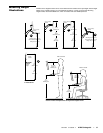
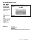
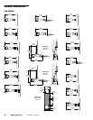
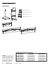
COMMAND POST BASE
Command Post Base,
2" x 2" Hole Pattern
Command Post Base,
3" x 3" Hole Pattern