


2
Product Category
8
10
9
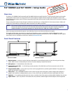
Extron TLP 1000MV
Use the Extron pry tool to remove the front faceplate of the
TLP 1000MV:
h
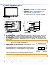
Menu button — activates the on-screen menus for calibrating
the unit (see page 3).
i
Reset button — allows the unit to be reset in any of four
different modes (see “Reset Modes” on page 4).
j
Reset LED — provides feedback about the reset status when the
user presses the reset button (see “Reset Modes” on page 4).
TLP 1000MV Reset Buttons and LED
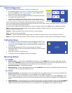
Rear Panel Features
Extron TLP 1000MV Extron TLP 1000TV
8
14
9
10
15
11
12
13
14
11
12
13
h
(Menu button),
i
(Reset button), and
j
(Reset LED) — see “TLP 1000MV Reset Buttons and LED“ above.
k
MTP Signal Adjustments — Three MTP signal adjustments are available for S-video luminance gain (VID/Y), S-video
chrominance gain (C), and sharpness (S). For composite video signals, the gain is controlled by the VID/Y adjustment.
l
MTP Input (optional) — A twisted pair cable, terminated with an RJ-45 connector, provides video and audio input
from an Extron MTP transmitter. For the TLP 1000TV, the MTP port is in the top surface of the recessed area, indicated
by the red arrow.
CAUTION: Ensure the MTP cable is connected to the MTP input and the network cable is connected to the
Network input. The voltages carried by the cables is different and connecting the MTP cable to the
Network input will damage the touchpanel unit.
m
Network and Power over Ethernet Connector — A twisted pair cable, terminated
with an RJ-45 connector, provides network connection. For the TLP 1000TV, the LAN
port is in the top surface of the recessed area, indicated by the blue arrow.
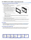
Extron recommends using the Power over Ethernet (PoE) power supply (provided).
Use straight-through cables to connect the LAN-IN port to a network switch and the
PWR LAN-OUT port to the LAN port of the touchpanel (see the figure to the right).
Connect the IEC power cord to a convenient 100 VAC to 240 VAC, 50-60 Hz power
source.
An Extron IP Link control interface must also be connected to the same network
domain as the TouchLink Panel. See the note on page 1 for a list of suggested models.
CAUTION: Do not connect any power supply before reading the Cautions about power supplies in the “Panel
Features” section of the TLP 1000MV and TLP 1000TV User Guide.
n
Power connector (optional) — Extron recommends using the PoE power supply (provided). As an alternative,
you may choose to connect the two pole, 3.5 mm captive screw connector from the 12 VDC, 1.0 A power supply (not
provided) to the power supply socket on the rear panel.
o
VESA mounting holes (TLP 1000TV only) — For use with the Extron LPVM-1 (part number 60-1099-02). For
complete mounting options of both the TLP 1000MV and TLP 1000TV, see the TLP 1000MV and TLP 1000TV User Guide.
PWR LAN-OUT LAN-IN
To Networ
k Switch
To TLP 1000
Power over Ethernet (PoE) Power Supply