


4
68-1909-50 Rev. A
03 11
Extron USA - West
Headquarters
+800.633.9876
Inside USA/Canada Only
+1.714.491.1500
+1.714.491.1517 FAX
Extron USA - East
+800.633.9876
Inside USA/Canada Only
+1.919.863.1794
+1.919.863.1797 FAX
Extron Europe
+800.3987.6673
Inside Europe Only
+31.33.453.4040
+31.33.453.4050 FAX
Extron Asia
+800.7339.8766
Inside Asia Only
+65.6383.4400
+65.6383.4664 FAX
Extron Japan
+81.3.3511.7655
+81.3.3511.7656 FAX
Extron China
+400.883.1568
Inside China Only
+86.21.3760.1568
+86.21.3760.1566 FAX
Extron Middle East
+971.4.2991800
+971.4.2991880 FAX
© 2011 Extron Electronics All rights reserved. www.extron.com
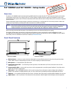
TLP 1000MV and TLP 1000TV • Setup Guide (Cont’d)
Wall-Mounting or Furniture-Mounting the TLP 1000MV
To mount the TLP 1000MV directly into a wall, follow these steps. The steps will be similar if the unit is mounted in furniture
(such as a podium or table).
1. Use the template provided to mark the wall at a
suitable location and cut a hole 10.06 inches (25.55 cm)
wide x 6.98 inches (17.73 cm) high.
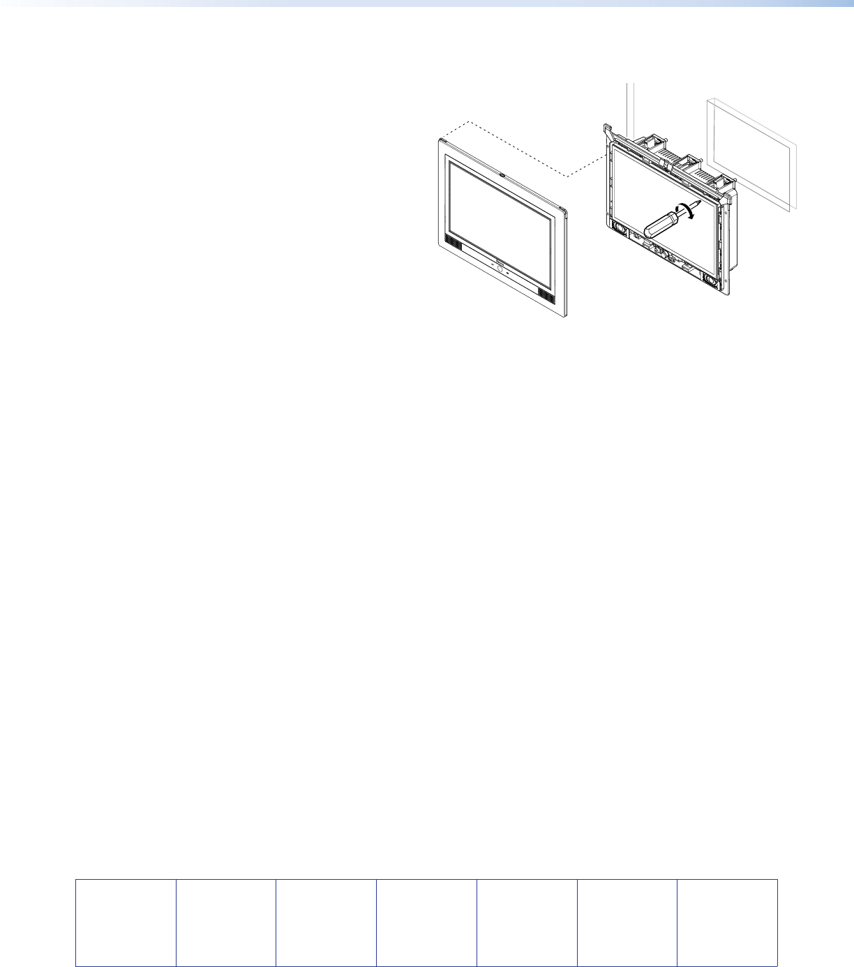
2. Unpack the TLP 1000MV and remove the faceplate.
3. Ensure all the locking arms are flush with the unit and
that the TLP 1000MV can fit into the hole. If necessary,
use a rasp or a coarse file to enlarge the hole.
4. Run the network and MTP cable connections inside the
wall to the hole, leaving enough slack in the cables to
connect them to the back of the TLP 1000MV.
5. Plug the cables into the rear panel connectors (see
page 2).
z Connect the LAN port to the PoE power supply and
network.
z Connect the RJ-45 MTP input.
z Optional: Extron recommends using the Power over Ethernet power supply provided. However, you may use the
LAN port only as a network connection and connect a 12 VDC, 1.0 A power supply (not provided) to the 2-pole
captive screw power input.
6. Push excess cables into the wall cavity.
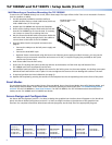
7. Ensure the five locking arms (three at the top and two at the bottom) are flush with top and bottom of the
TLP 1000MV and fit the touchpanel into the hole.
8. Use a Phillips head screwdriver to tighten the screws for the locking arms. As the screws tighten, the locking arms rotate
behind the wall and hold the unit in place. Do not overtighten the screws as this can damage the catches or the wall.
9. If required, perform the initial calibration (see page 3).
10. Replace the faceplate by pressing the catches on the faceplate into the corresponding holes on the front of the panel.
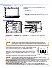
Reset Modes
The touchpanels have four reset modes: Factory Firmware Mode, Run or Stop Events Mode, Reset All IP Settings Mode, and
Reset Factory Defaults Mode. These modes can be initiated by pressing the reset button (see “TLP 1000MV Reset Buttons
and LED“ for the TLP 1000MV or “Rear Panel Features“ for the TLP 1000TV). For full information about these different
modes, see the TLP 1000MV and TLP 1000TV User Guide.
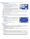
Screen Design and Conguration
Use Extron GUI Configurator (version 1.2 or later) to design the graphical user interface that will appear on the TouchLink
panel. Use Extron Global Configurator (version 3.1 or later) to assign functions to the elements of the graphical user
interface. For complete information about these software programs, see the help file of the appropriate program.
Faceplate Snaps to Unit
(4 plcs ea side)
Tighten Screws to
Rotate Locking Arms