


- 24 -
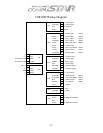
CONNECTOR 7
(Pre-wired Shock Sensor)
Pin 1 Black
-Shock sensor (-) negative ground input.
Pin 2 White-Shock sensor 2
nd
stage (-) negative input. (Instant trigger)
Pin 3 Red
-Shock sensor 12-volt (+) positive input.
Pin 4 Yellow
-Shock sensor 1
st
stage (-) negative input. (Warn away)
CONNECTOR 8
(Optional add on sensors; i.e. proximity)
Pin 1 Gray/White- Optional sensor 1
st
stage (-) negative input. (Warn away)
Pin 2 Black/White-Optional sensor 2
nd
stage (-) negative input. (Instant trigger)
CONNECTOR 9
(Pre-wired Remote Paging Sensor or R.P.S.)
Pin 1 Black-R.P.S. sensor (-) negative ground input.
Pin 2 White-R.P.S. sensor (-) negative paging input.
Pin 3 Red
-R.P.S. sensor 12-volt (+) positive input.
Pin 4 Yellow- R.P.S. sensor 9-volt (+) positive L.E.D. output
CONNECTOR 10
(Optional Temperature sensor)
Pin 1 Gray-12-volt (+) positive output. This wire will provide 12-volt (+) positive to
temperature sensor.
Pin 2 Brown-Temp sensor (-) negative input. This wire will activate remote start when
provided a (-) negative input. (Note: If vehicle is remotely started, a (-) negative
input will turn the vehicle off.)
Pin 3 Black
-Temp sensor (-) negative ground output.