


- 29 -
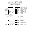
Pin 6 Green –Ignition input. This wire must be connected to the vehicles ignition to
trigger remote programming. The proper wire will test 0-volts with the key in the
off position, 12-volts (+) positive while the key is in the on position and 12-volts
(+) positive during crank.
Pin 7 Violet- Dome light 250mA (-) negative output. This is an optional output that will
provide a 30 second (-) negative output after system is unlocked for dome-light
supervision.
Pin 8 Orange
- Factory alarm re-arm 250mA (-) negative output. This is an optional
output that will provide a (-) negative pulse output during lock, after crank and after
ignition shut down.
Pin 9 Orange/White- Factory alarm disarm 250mA (-) negative output. This is an
optional output that will provide a (-) negative pulse output during unlock and
before ignition is turned on.
CONNECTOR 3
Pin 1 Gray/Black- Hood-pin (-) negative input. This is an optional input that will
monitor when the vehicles hood is opened.. (Note: This wire will also trigger alarm
when system is armed.)
.
Pin 2 Violet/Black- Trunk-pin (-) negative input. This is an optional input that will
monitor when the vehicles trunk is opened. (Note: This wire will also trigger alarm
when system is armed.)
Pin 3 Red/White- Door trigger (-) negative input. This wire monitors (-) negative trigger
door-pins. The proper wire will provide a (-) negative trigger only when the doors
are opened.
Pin 4 Red
- Door trigger (+) positive input. This wire monitors (+) positive trigger door-
pins. The proper wire will provide a (+) positive trigger only when the doors are
opened.
Pin 5 Black /White- Optional sensor 2
nd
stage (-) negative input. (Instant trigger)
Pin 6 Gray/White- Optional sensor 1
st
stage (-) negative input. (Warn away)