10
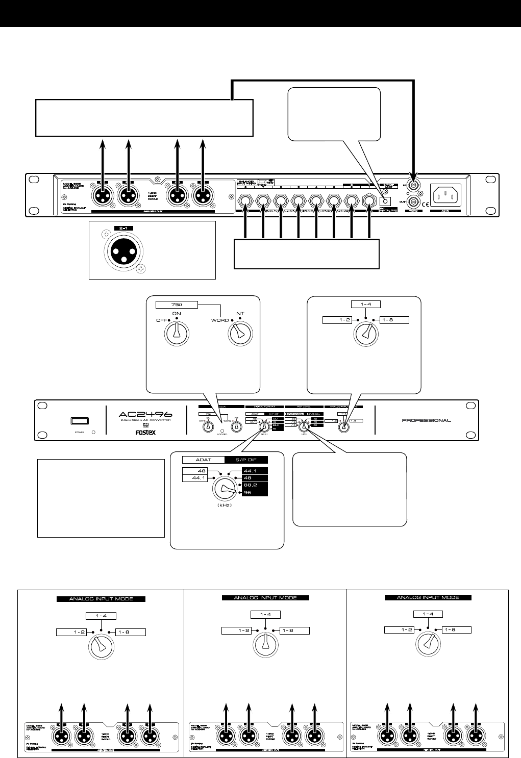
If WORD clock is input from
digital equipment, set the
CLOCK SW to "WORD" and
the terminate SW to "ON."
This is switched in accor-
dance to the analog input type
(Refer to explanation below).
Set FS (44.1/48/88.2/96kHz)
to match the equipment con-
nected. Above is an example
of setting to 96kHz.
Set the AC2496 reference level
to match the output level (bal-
anced/unbalanced line) of ex-
ternal equipment connected
such as an analog mixer.
Extension example after installing a Model 8355
When the optional Model 8355 (8ch AES/EBU card) is installed, the AC2496 can be utilized as an
analog-AES/EBU converter. Unlike the previous example, this setup can output 24 bit 88.2kHz/24 bit
96kHz digital signals.
In compliance to the DIGI-
TAL FORMAT switch set-
ting, adat or S/P DIF digital
signals will also be output.
Analog Inputs (1-8)
Digital equipment installed with
AES/EBU input ports
(Refer to explanation below)
WORD clock
AES/EBU digital signal
Signals applied to inputs 1 and 2 will be output in
the AES/EBU format from output connectors 1-2,
3-4, 5-6 and 7-8.
Signals applied to inputs 1-4 will be output in the
AES/EBU format from output connectors 1-2 and
3-4 (5-6 and 7-8).
Two channels each of the signals applied to in-
puts 1-8 will be output in the AES/EBU format from
their respective output connectors.
The AES/EBU format output signals are output from each connector as shown below in compliance
to the front panel setting ANALOG INPUT MODE switch.
• Set of the AC2496
• Connecting example
PIN assignments
Pin 1 = GND
Pin 2 = HOT
Pin 3 = COLD
If it is to be set to 44.1kHz and
48kHz, it is okay to set to FS for
ADAT or S/P DIF.
However, digital signals (adat or
S/P DIF) corresponding to the set-
ting will be output from the optical
DIGITAL OUT connector.
ch1/2ch1/2ch1/2
ch1/2
ch1/2
ch3/4
ch1/2
ch3/4
ch1/2
ch3/4
ch5/6
ch7/8
