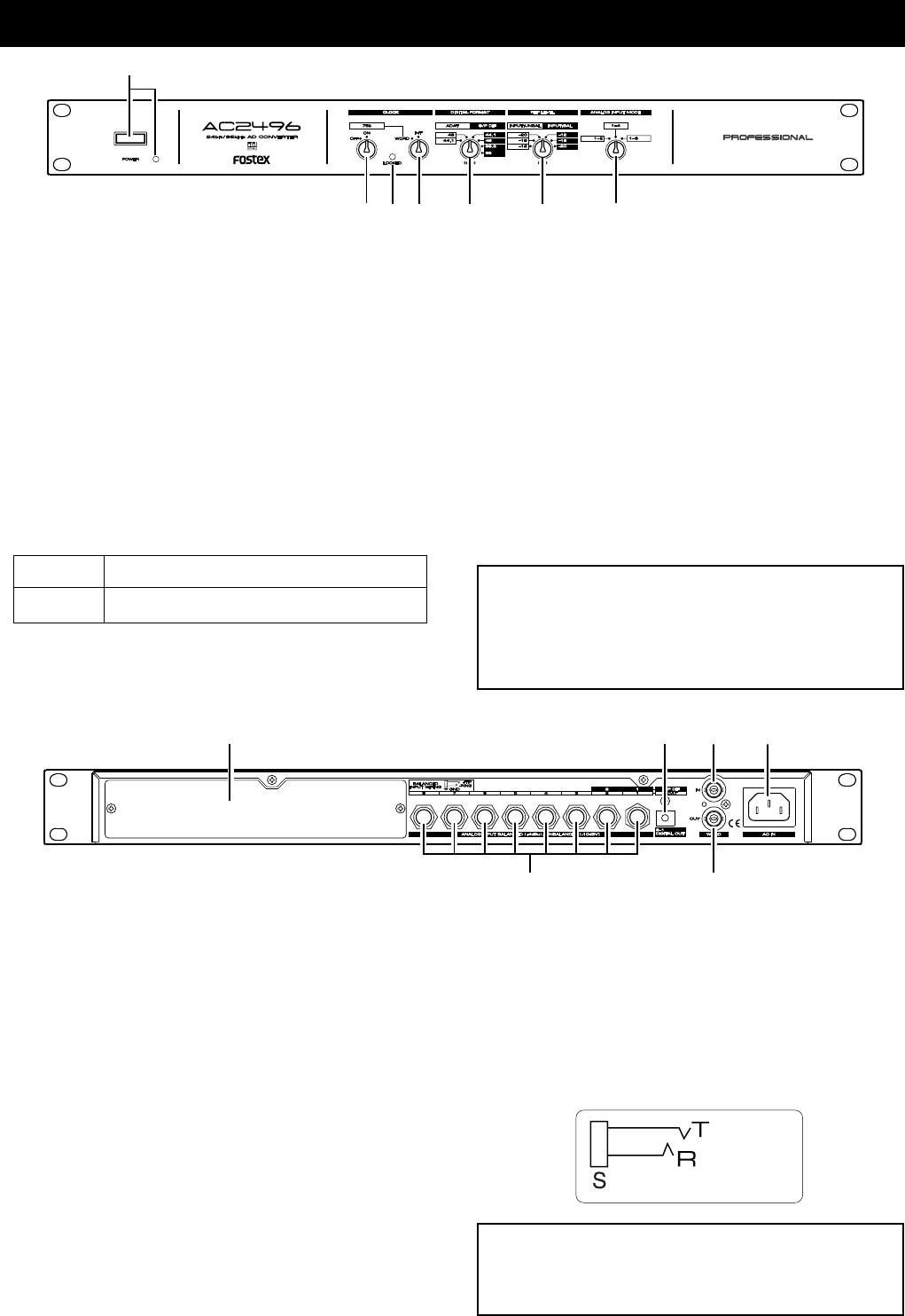
4
1
2
3
45 6 7
1. Power switch/Power LED
The main power switch for the AC2496.
The power LED (green) will light when power is
switched ON.
2. WORD IN termination switch
This must be switched ON when input signals from
WORD IN is to be terminated by 75 ohms.
3. LOCKED indicator
This will light up when the CLOCK switch is set to
"WORD" and locked onto the external WORD clock.
4. Clock switch
This is for setup of the AC2496 operating clock.
6. Reference level selecting switch
This switch selects the reference level (all channels
simultaneously) of the analog input (balance or un-
balance). Both balance and unbalance can be selected
to -20dB/-18dB/-12dB (Refer to <Notes> on the next
page).
7. Analog input mode selecting switch
This switch becomes effective when the DIGITAL FOR-
MAT switch is set to "adat" and if the optional Model
8355 has been installed; the signal applied to the ana-
log input connector can be assigned to the desired
channel. In general, these are selected in accordance
to the number of BUSS OUT of a connected analog
mixer.
8. Blank panel
This blank panel is removed when installing the op-
tional Model 8355 (AES/EBU card) or the Model 5045
(8 channel AD card). In regards to installation of the
options, refer to the manual included with the cards.
9. DIGITAL OUT 1-8 connectors (Optical)
Digital equipment provided with optical DIGITAL IN
are connected here. The type of digital signals (adat
or S/P DIF) selected by the DIGITAL FORMAT switch
will be output here.
10. WORD IN connector (BNC type)
The WORD clock signal from external digital equip-
ment is input here to match the phase with digital
equipment provided with WORD OUT.
11. AC IN connector
The AC cable included with the AC2496 is connected
here.
12. WORD OUT connector (BNC type)
The AC2496 WORD clock signal for external digital
equipment is output here.
13. Analog input connector (TRS phone jack)
This is connected to BUSS OUT (or GROUP OUT) of
the analog mixer (Refer to <Note> on the next page).
These connectors can accept both balanced (+4dBu)
and unbalanced (-10dBV) analog signals.
Names and functions of each section
"INT" Operates by the AC2496 crystal.
"WORD" Synchronizes with the external WORD clock.
8
910
11
12
13
<Notes on switching>
Always switch off the main power to the AC2496
before changing the various selecting switches.
If the switches are manipulated with the main
power switched on, it could create noise.
<Notes when connecting cables>
When plugging or unplugging the interconnecting
cables, be sure to do so after switching off the power
to the AC2496.
5. Digital format selecting switch
This selects the digital output format (adat, S/P DIF
or AES/EBU). It can also be selected to 44.1kHz, 48kHz,
88.2kHz or 96kHz (44.1/48kHz only for adat output).
T: HOT
R: COLD
S: GND


