


E-8
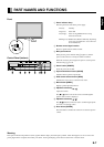
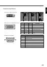
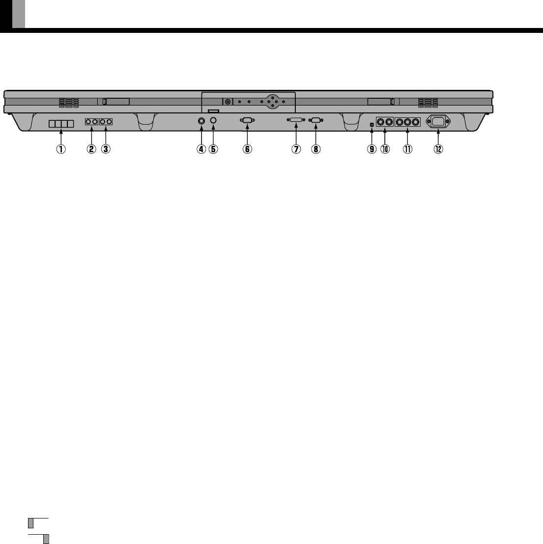
1 External speaker output terminal (EXT SP)
Connect this terminal to the optionally available speaker. (Use a speaker with 4 to 16 Ω.)
*See the speaker instruction manual for more information.
2 Sound 1 input terminal (AUDIO 1 INPUT)
Connect this terminal to the sound output terminal of your VCR, etc.
3 Sound 2 input terminal (AUDIO 2 INPUT)
Connect this terminal to the sound output terminal of your VCR, etc.
4 Video input terminal (VIDEO INPUT)
Connect this terminal to the video output terminal of your VCR or video disk player.
5 S-video input terminal (S-VIDEO INPUT)
Connect this terminal to the S-video output terminal of your VCR or video disk player.
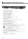
6 RS-232C terminal (RS-232C)
This terminal is provided for you to control the display from the PC. Connect it to the RS-232C terminal on the PC.
When connecting a cable, attach a ferrite core to the cable. (See P. E-12.)
7 RGB 1 input terminal (RGB 1 INPUT/DVI-D)
Connect this terminal to the PC’s display (digital RGB) output terminal.
*The connection cable No.88741-8000 made by
molex Inc. is recommanded.
8 RGB 2 input terminal (RGB 2 INPUT/mD-sub)
Connect this terminal to the PC’s display (analog RGB) output terminal or decoder (digital broadcast tuner, etc.) output terminal.
9 RGB 3 synchronization switch (SYNC SW TTL/ANALOG (75 Ω))
This switch is used to terminate horizontal (H) terminal and vertical (V) terminal, out of RGB3 input terminals, with 75 Ω .
TTL : Used when sending RGB signals from the PC to the RGB 3 terminal
ANALOG (75 Ω): Used when sending analog synchronization signals to the RGB 3 terminal
0+A RGB 3 input terminal (RGB 3 INPUT/BNC)
Connect this terminal to the PC's display (analog RGB) output terminal or decoder (digital broadcast tuner,etc.) output terminal.
*When RGB3 input terminal is connected, Comp.video mode is not available. (See P. E-33.)
A Component video input terminal (COMPONENT VIDEO INPUT)
Connect this terminal to the component video output (color difference output) terminal of your HDTV unit or DVD player.
*When Comp.video input terminal is connected, RGB3 mode is not available. (See P. E-33.)
B Power input terminal
Connect this terminal to the power cable supplied with the display.
When connecting a cable,attach a ferrite core to the cable. (See P. E-12)
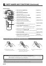
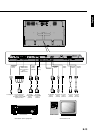
PART NAMES AND FUNCTIONS (Continued)
Bottom