


Tracer 2000 DVR user manual
Version 3.0 Page 14 of 36
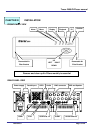
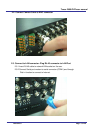
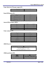
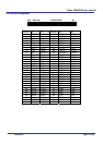
Power Switch for ATX power supply (JP1)
Signals JP1
Power ON/OFF 1-3
Reset/LED/Speaker (JP1)
Signals JP1
Power LED, Pin 9+, Pin10- 9-10
External speaker 14-20
HDD LED, Pin8+, Pin7- 7-8
System reset switch 5-6
SUSLED Pin4+, Pin2- 2-4
PS. For the AT system (short pin 10 & pin12) for power on
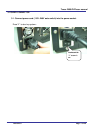
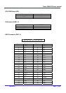
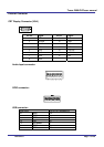
Internal USB connector (USB2)
Signals USB2-1 USB2-2
Power 1 10
Data - 3 8
Data + 5 6
USB GND 7 4
CHS GND 9 2
Power connector (P1)
Signals P1
+12V 10
+5V 4,6,19,20
-12V 12
-5V 18
+3.3V 1,2,11
5VSB 9
PS-ON 14
POWER-OK 8
Ground 3,5,7,13,15,16,17
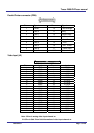
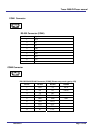
CMOS Clear (J1)
J1
POWER OFF and Move jumper from pin 1-2 to pin2-3 of J1,
Reminding POWER OFF 1minute.
Then Move JUMPER back to 1-2 OF J1
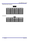
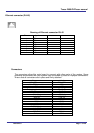
COM2 mode Select (JP3)
Mode JP3
RS-232 3-5, 4-6, 9-11, 10-12, 17-18
RS-422 1-3, 2-4, 7-9, 8-10, 15-16
RS-485 1-3, 2-4, 7-9, 8-10, 13-14