


Tracer 2000 DVR user manual
Version 3.0 Page 21 of 36
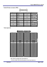
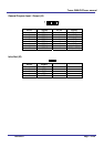
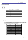
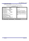
Ethernet connector (RJ-45)
Drawing of Ethernet connector RJ-45
Pin no. signals
1 TX+
2 TX-
3 RX+
4 NC
5 NC
6 RX-
7 NC
8 NC
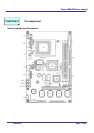
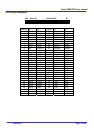
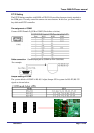
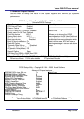
Connectors
The connectors allow this main board to connect with other parts of the system. Some
problems encountered with your system may be caused by loose or improper connections.
Ensure that all connectors are in place and firmly attached.
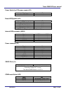
Component Label
HDD (IDE) connector IDE 1,IDE2
Slim FDD connector FDC
Internal USB connector USB2
Reset switch connector JP1 (6-5)
External speaker connector JP1 (14-20)
HDD LED connector JP1 (7-8)
External power connector P1
Serial Port COM1,2
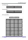
Audio OUT LINE_OUT
Audio IN LINE_IN
MIC MIC_IN
CD IN CD_IN
LAN RJ-45
Video INPUT J2
CMOS RAM clear J1
Audio/GPIO J3
IR IR
CPU FAN FAN1,2
Printer PRN