


PREPARATION
13
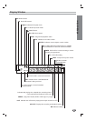
Connections (Continued)
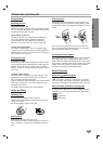
Basic TV Connections
Make one of the following connections, depending on
the capabilities of your existing equipment.
Due to Macrovision encoding, you may not be able to
view DVDs when connecting the DVD+VCR to a
TV/VCR combination unit.
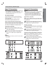
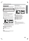
RF coaxial connection
Connect the RF OUT jack on the DVD+VCR to the
antenna in jack on the TV using the 75-ohm Coaxial
Cable supplied (R).
If you use this connection, tune the TV to the
DVD+VCR’s RF output channel (CH 3 or 4).
How to set the DVD+VCR’s RF output channel
When the VCR is turned off,
press and hold CH (v or V)
on the front panel for about five seconds to toggle the
RF output channel between CH 03 and CH 04. The “RF
03” or “RF 04” is displayed in the display window.
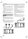
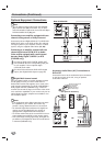
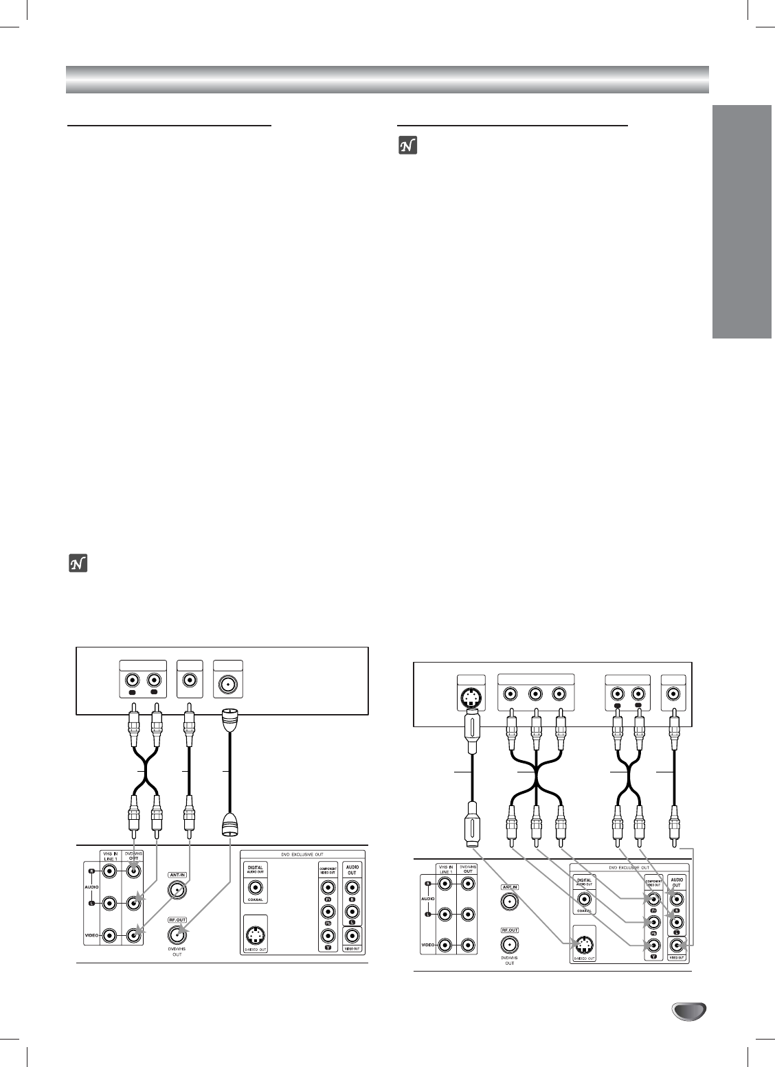
Audio/Video connection
11
Connect the DVD/VHS VIDEO OUT jack on the
DVD+VCR to the video in jack on the TV using the
video cable supplied (V).
22
Connect the Left and Right DVD/VHS AUDIO OUT
jacks of the DVD+VCR to the audio left/right in
jacks on the TV (A1) using the supplied audio
cables.
Notes
If you use this connection, set the TV’s source selec-
tor to VIDEO.
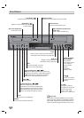
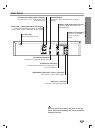
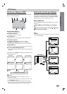
Optional TV Connections
Notes
You can ONLY watch and listen to DVD playback
through one of the following connections.
For using S-VIDEO OUT or COMPONENT VIDEO
OUT jack, set the TV Output Select mode on the
SETUP menu to corresponding mode. See page 19.
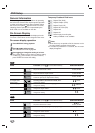
Audio/Video connection
11
Connect the VIDEO OUT jack on the DVD+VCR to
the video in jack on the TV using the video cable
supplied (V).
22
Connect the Left and Right AUDIO OUT jacks of
the DVD+VCR to the audio left/right in jacks on the
TV (A2) using the supplied audio cables.
S-Video connection
11
Connect the S-VIDEO OUT jack on the DVD+VCR
to the S-Video in jack on the TV using the supplied
S-Video cable (S).
22
Connect the Left and Right AUDIO OUT jacks of
the DVD+VCR to the audio left/right in jacks on the
TV (A2) using the supplied audio cables.
Component Video (Color Stream
®
) connection
11
Connect the COMPONENT VIDEO OUT jacks on
the DVD+VCR to the corresponding in jacks on the
TV using an optional Y Pb Pr cable (C).
22
Connect the Left and Right AUDIO OUT jacks of
the DVD+VCR to the audio left/right in jacks on the
TV (A2) using the supplied audio cables.
L
R
AUDIO INPUT
VIDEO
INPUT
ANTENNA
INPUT
Rear of TV
Rear of DVD+VCR
A1 V R
L
R
Y
Pb
Pr
COMPONENT VIDEO INPUT
AUDIO INPUT
L
VIDEO
INPUT
S-VIDEO
INPUT
Rear of TV
Rear of DVD+VCR
S A2 VC