


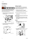
Installation
313259D 17
Setup
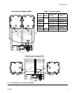
For heating hoppers only:
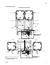
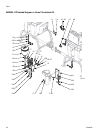
See fluid schematic on page 9 and parts on page 21.
NOTE: To ensure a leak-proof seal, use PTFE tape
on all pipe thread connections.
1. Connect A and B fluid hoses to shutoff check valve
outlets (H).
2. Connect elbow fitting (17) in pump outlet (3) and
elbow fitting (17) on heater inlet (A) with tubing (16).
3. Connect fitting (7) in the heater fluid outlet (A) and
tee fitting (13) with tubing (4). Connect tee
fitting (13) and fittings (7) in the hopper side ports
with tubing (4).
4. Connect fittings (31) to elbow in bottom outlet of
hoppers and tee fitting (30) with tubing (29). Con-
nect tee fitting (30) and the pump (3) inlet fitting (31)
with tubing (29).
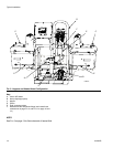
For heating heated hose only:
See fluid schematic on page 13 and parts on page 22.
1. Connect A and B fluid hoses to shutoff check valve
fluid outlets (H).
2. Connect elbow fitting (17) in pump outlet (3) and
elbow fitting (17) on heater inlet (A) with tubing (16).
3. Connect fitting (7) in the heater fluid outlet (A) and
tee fitting (13) with tubing (4).
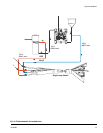
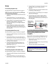
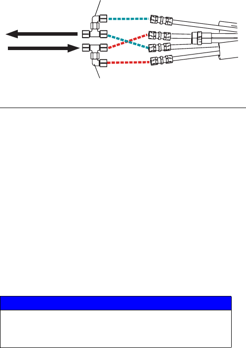
4. Connect tee fitting (42) and elbow fitting (41) to
recirculation inlets and outlet connections of the
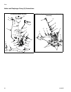
heated hose. See F
IG. 10.
5. Connect elbow fitting (7) to 1-1/2 gallon tank mani-
fold (23) with tubing (4).
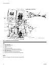
For heating hoppers and heated hose:
See fluid schematic on page 11 and parts on page 20.
1. Connect A and B fluid hoses to shutoff check valve
outlets (H).
2. Connect elbow fitting (17) in pump outlet (3) and
elbow fitting (17) on heater inlet (A) with tubing (16).
3. Connect fitting (7) in the heater fluid outlet (A) and
tee fitting (13) to hose circulation inlet with
tubing (4).
4. Connect tee fitting (13) from hose circulation return
to tee fitting (13) with tubing (4).
5. Connect tee fitting (13) and fittings (7) in the hopper
side ports with tubing (4).
6. Connect fittings (31) to elbow in bottom outlet of
hoppers and tee fitting (30) with tubing (29). Con-
nect tee fitting (30) and the pump (3) inlet fitting (31)
with tubing (29).
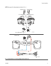
Connecting Additional Hose
Lengths
Up to six 50 ft (15.2 m) sections of heated hose can be
attached for a maximum total length of 300 ft (91.4 m).
1. Remove plastic u-turn fittings at the end of the
heated hose assembly.
2. Connect the next length of hose, using union fittings
supplied with the hose.
3. Tubes are color coded. Connect like colors.
F
IG. 10: Recirculation Inlet and Outlet Connections
NOTICE
To prevent cross-contamination, ensure you connect
“A” side fluid hose to “A” side fluid hose on additional
heated hose.
Hopper Inlet or
1-1/2 gallon tank
manifold
Heater Outlet
ti19230a
Blue hose connections
Red hose connections