


25 OPERATION
Operation
The tuner will run through the list of preset
stations, stopping for five seconds at each one.
Press the button again to stop the scan at your
desired station.
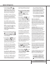
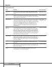
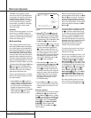
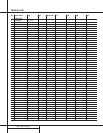
• To view a list of the stations entered in the
preset memory, press the OSD button s to
bring up the Full-OSD screen while the tuner is
in use and then press the Memory button
p.The video display screen will show the
first 16 stations that have been preset, as
shown in Figure 7.
Figure 7
The word NONE simply indicates that no sta-
tion information has been entered and that the
memory slot is available.To view the remaining
stations, press the Numeric Keys q for a
preset number not on the list, and the display
will change.
Tape Recording
In normal operation, the audio or video source
selected for listening through the AVR 500 is
sent to the record outputs.This means that any
program you are watching or listening to may
be recorded simply by placing machines con-
nected to the outputs for Tape Out g or
Video 1 ™ in the record mode.
When a digital audio recorder is connected to
the digital outputs ª, you are able to record
the digital signal to a CD-R, MiniDisc or other
digital recording system.
NOTES:
• The digital outputs are active only when a
digital signal is present, and they do not
convert an analog input to a digital signal,
or change the format of the digital signal.
In additonal, the digital recorder must be
compatible with the output signal. For
example, the PCM digital input from a CD
player may be recorded on a CD-R or
MiniDisc, but Dolby Digital or DTS signals
may not.
• Please make certain that you are aware of
any copyright restrictions on any material you
copy. Unauthorized duplication of copyrighted
materials is prohibited by Federal law.
Output-Level Trim Adjustment
Normal output-level adjustment for the
AVR 500 is established using the Test Tone, as
outlined on page 18. In some cases, however, it
may be desirable to adjust the output levels
using program material such as a test disc, or a
selection you are familiar with.Additionally, the
output level for the subwoofer can only be
adjusted using this procedure.
To adjust the output levels using program
material, first set the reference volume for the
front-left and front-right channels using the
Volume Control ˆ .If you wish to vary
the difference between the left and right chan-
nels, use the Balance Control 7.
Once the reference level has been set, press
the Channel Select button
h
and note that
FRONT L LEV will appear in the Main
Information Display V. To change the
level, first press the Set button i
31
, and
then use the Selector buttons
34
or the
⁄
/
¤
buttons
g
to raise or lower the level.
DO NOT use the volume control, as this will
alter the reference setting.
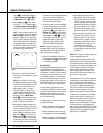
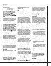
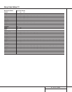
Adjusting the output-level trim is easier when
the Full-OSD system is used.To do this, first
press the Channel Select Button
h
and
then press the OSD button so that the display
shows all available speaker positions as shown
in Figure 8. Note that there will be a flashing
pointer under the FL, or front-left position.
When the Set button i is pressed to start
adjustments, the pointer will stop flashing.
During adjustments the numbers will increase
or decrease to indicate the change from the
reference-level setting.
Figure 8
Once the change has been made, press the Set
button i
31
and then press the Selector
buttons
34
or the
⁄
/
¤
buttons
g
to select
the next output channel location that you wish
to adjust.To adjust the subwoofer level, press
the Selector buttons
34
or the
⁄
/
¤
buttons
g
until S-WOOFER LEV appears in the
Main Information Display V.
Press the Set button i
31
when the name
of the desired channel appears in the Main
Information Display V, and follow the
instructions shown earlier to adjust the level.
Repeat the procedure as needed until all chan-
nels requiring adjustment have been set.When
all adjustments have been made and no further
adjustments are made for twenty seconds, the
AVR 500 will return to normal operation.
NOTE: The output levels may be separately
trimmed for each digital and analog surround
mode. If you wish to have different trim levels for
a specific mode, select that mode using the front
panel buttons
(ÓÔÒ
Ú or on
the remote control and follow the instructions in
the steps shown above.
6-Channel Direct Input
The AVR 500 is equipped for future expansion
through the use of optional, external adapters
for formats that the AVR 500 may not be capa-
ble of processing.When an adapter is connected
to the 6-Channel Direct Input §, you may
select it by pressing the 6-Ch Input Selector
l
#
.
Note that when the 6-Channel Direct Input is in
use, you may not select a surround mode, as
the external decoder determines processing. In
addition, there is no signal at the record out-
puts when the 6-Channel Direct Input is in use.
Memory Backup
This product is equipped with a memory backup
system that preserves tuner presets and system
configuration information if the unit is acciden-
tally unplugged or subjected to a power out-
age.This memory will last for approximately
two weeks, after which time all information
must be reentered.
31
MODE: DOLBY PRO LOGIC
FL C FR
0 0 0
S-W
0
SL SR
0 0
MASTER VOLUME:20DB
32
MEMORY TABLE
1:FM102.70 2:FM 94.70
3:AM 1070 4:AM 1130
5:FM 89.90 6:FM 91.50
7:FM 95.50 8:FM106.70
9:AM 790 10:AM 1150
11:FM105.30 12:FM101.10
13:AM 640 14:AM 1110
15:FM 98.70 16:NONE