5
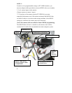
MDVR main Harness wire connections
(25-pin connector)
Red – Power (direct 12 volt positive)
Black – Ground (12 volt negative)
Yellow – Ignition (switched 12 volt positive)
Green – Trigger 1
Orange – Trigger 2
Brown – Trigger 3
Blue – Trigger 4
Gray – Trigger 5
NOTE 1:
Trigger connections are pre-set (default) to activate on positive
Switching. They can be changed to negative switching by changing
MDVR settings in trigger Menu. (High = Positive / Low = Negative)
NOTE 2:
For correct operation, it is very important to connect the main power to a
constant 12V supply (not switched) and the Ignition trigger to the
ignition power supply (switched).
• RCA to RCA 6 foot Cable # GSM70024
Monitor Video OUT to MDVR Video IN (use yellow connectors)
MDVR Video OUT to Monitor Video IN (use white connectors)
Red connector not used
(see NOTE 3A below)
• RCA to Camera input adaptor. (# GSM70026)
(Use yellow RCA connector - Red not used)


