


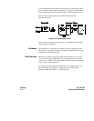
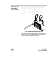

You can connect the probe directly to the test pins on your target system.
To do so, the pins must be 0.63 mm (0.025 in.) square pins or round pins
with a diameter of between 0.66 mm (0.026 in.) and 0.84 mm (0.33 in.).
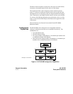
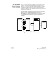
Each probe has an input impedance of 100 kΩ in parallel with
approximately 8 pF.
Probescanbegroundedinoneoftwoways:acommonpodgroundanda
probe ground for each probe.
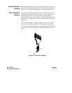
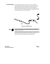
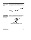
Grabbers The grabbers have a hook that fits around IC pins and component leads
and connects to the probes and the ground leads. The grabbers have been
designed to fit on adjacent IC pins.
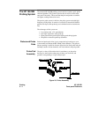
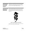
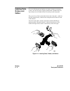
Pod Grounds Eachpodisgroundedbyapodgroundleadthatshouldalwaysbeused.
You can connect the ground lead directly to a ground pin on your target
system or use a grabber. The grabber connects to the ground lead the same
way it connects to the probe lead.
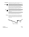
To connect the ground lead to grounded pins on your target system, the
pins must be 0.63 mm (0.025 in.) square pins or round pins with a
diameter of 0.66 mm (0.026 in.) to 0.84 (0.033 in.).
Figure 2-5. Probe Input Circuit
Probing HP 16510B
2 - 6 Front-panel Reference