


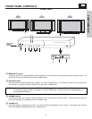
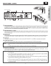
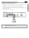
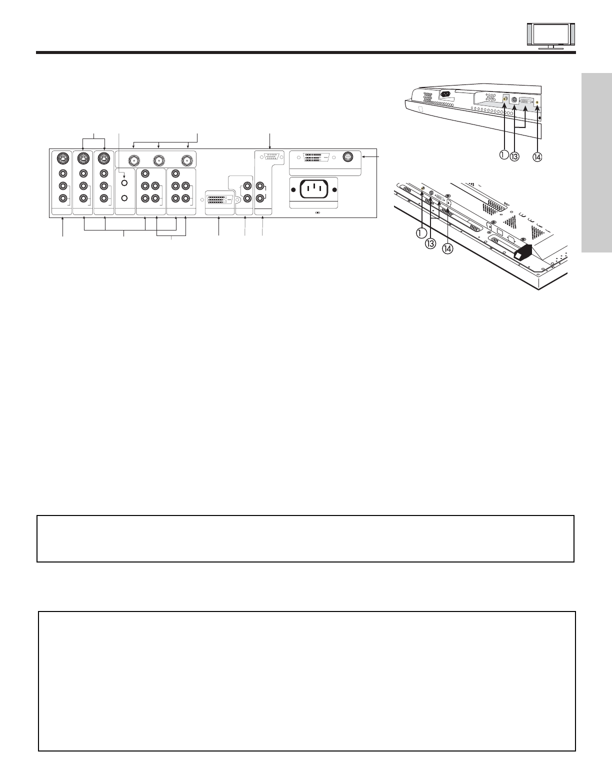
REAR PANEL JACKS
11
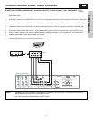
ቧ Component: Y-P
B
P
R
Inputs
Inputs 1 and 2 provide Y-P
B
P
R
jacks for connecting equipment with this capability, such as a DVD player or Set Top Box. You may
use composite video signal for INPUT 2. INPUT 1 does not accept composite video signal.
NOTES: 1. DO NOT connect composite VIDEO and S-VIDEO to Input 3, 4 or 5 at the same time. S-Video has a higher priority
over video input.
2. Your component outputs may be labeled Y, B-Y, and R-Y. In this case, connect the components B-Y output to the AVC
Box’s P
B
input and the components R-Y output to the AVC Box’s P
R
input.
3. Your component outputs may be labeled Y-C
B
C
R
. In this case, connect the component C
B
output to the AVC Box’s
P
B
input and the component C
R
output to the AVC Box’s P
R
input.
4. It may be necessary to adjust TINT to obtain optimum picture quality when using the Y-P
B
P
R
inputs (See page 44).
5. To ensure no copyright infringement, the MONITOR OUT output will be abnormal, when using the Y-P
B
P
R
jacks, RGB
and DVI-HDTV inputs.
ቢ Antenna Input/Output
The remote control allows you to switch between two separate 75-Ohm RF antenna inputs, ANT A and ANT B. ANT A input can
be displayed as a main picture or sub-picture. ANT B can only be displayed as a main picture (ANT B cannot be displayed as a
sub-picture). The antenna output labeled “TO CONVERTER” allows the ANT A connection to pass directly to a different source
such as a cable box, only when ANT B is displayed as a main picture.
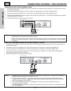
ባ Audio/Video Inputs 1, 2, 3 and 4
The VID1~VID4 buttons will select each video source each time they are pressed. Use the audio and video inputs to connect
external devices, such as VCRs, camcorders, laserdisc players, DVD players etc. (if you have mono sound, insert the audio cable
into the left audio jack).
ቤ MONITOR OUT
These jacks provide fixed audio and video signals (ANT A/B, INPUT 2~5) which are used for recording. Use the S-VIDEO Output
for high quality video output. Component signal to Input 1 and 2, RGB and DVI-HDTV inputs will not have monitor output.
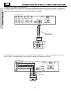
ብ AUDIO OUT
These jacks provide fixed audio output for all audio sources (ANT A/B, INPUT1~5, and RGB) to a separate stereo amplifier.
ቦ S-VIDEO Inputs 3 and 4
Inputs 3 and 4 provide S-VIDEO (Super Video) jacks for connecting equipment with S-VIDEO output capability.
ባ
ቤ
ቦ
ቧ
ቨ
ቪ
ቫ
ቭ
ብ
ቩ
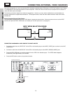
REAR PANEL OF THE AVC CENTER
P
B
P
R
P
B
P
R
Y/VIDEO
R
L/(MONO)
AUDIO
L
R
S-VIDEO
VIDEO
AUDIO
R
S-VIDEO
VIDEO
AUDIO
R
S-VIDEO
VIDEO
MONITOR OUT INPUT 4 INPUT 3 IR BLASTER
L/(MONO)L/(MONO)
AUDIO
Y
R
L/(MONO)
AUDIO
INPUT 2 INPUT 1
ANT B
TO CONVERTER
ANT A
DVI-HDTV
INPUT 1
L
AUDIO
R
AUDIO OUT
ANALOG INPUT
L/(MONO)
R
AUDIO
RGB
TruBass SRS and symbol are trademarks of SRS Labs, Inc.
AC IN
TO MONITOR
Please use HITACHI specified cable.
ቢ
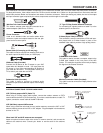
NOTES: 1. You may use VIDEO or S-VIDEO inputs to connect to INPUT 3 and 4, but only one of these inputs may be used at a
time.
2. S-VIDEO output may be used for recording, only when the input is of S-VIDEO type.
2
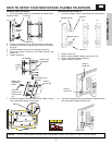
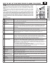
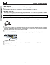
FIRST TIME USE
2
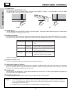
32”/42” Monitor Bottom View
50” Monitor Bottom View