


16
CONNECTING EXTERNAL VIDEO SOURCES
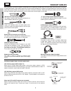
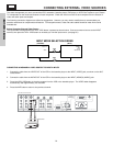
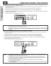
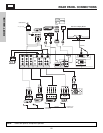
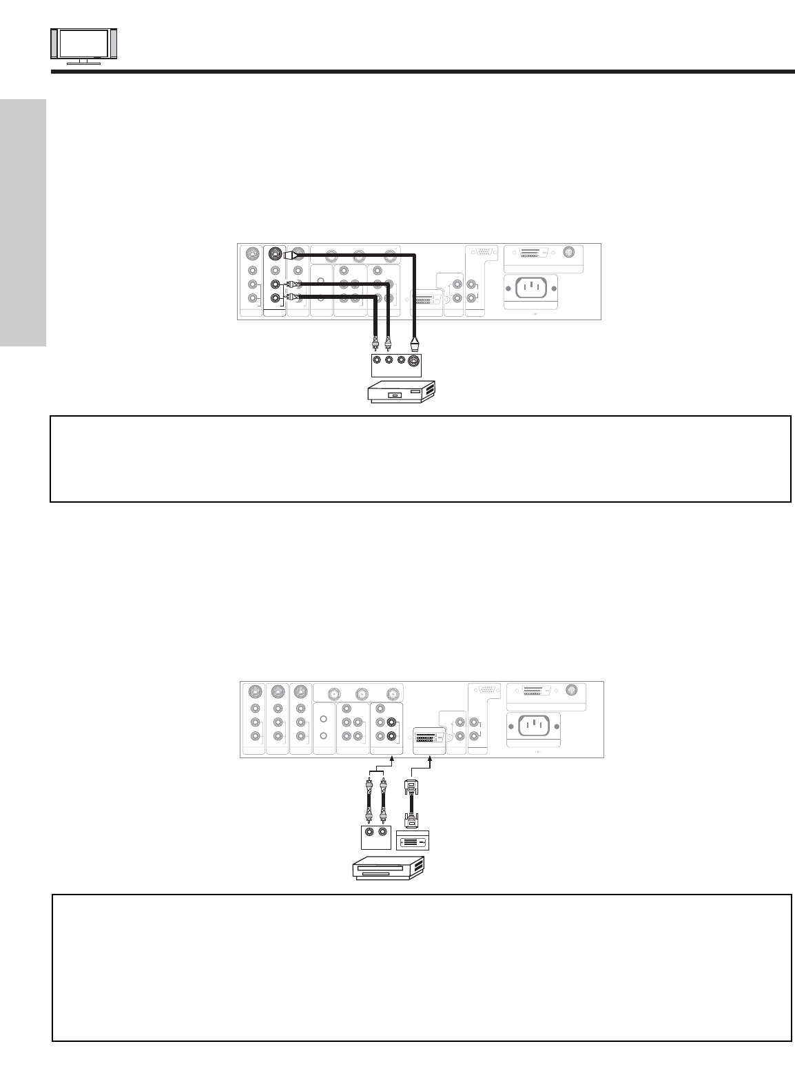
CONNECTING S-VIDEO VCR OR LASERDISC PLAYER
1. Connect the cable from the S-VIDEO OUT of the S-VHS VCR or the laserdisc player to the INPUT (S-VIDEO) jack, as shown
on the AVC Center below.
2. Connect the cable from the AUDIO OUT R of the VCR or the laserdisc player to the INPUT (AUDIO/R) jack.
3. Connect the cable from the AUDIO OUT L of the VCR or the laserdisc player to the INPUT (AUDIO/L) jack.
4. Press the VID3~VID5 button to view the program from the VCR or laserdisc player. The VIDEO label disappears automatically
after approximately four seconds.
5. Press the ANT button to return to the previous channel.
NOTES: 1. Completely insert the connection cord plugs when connecting to rear panel jacks. The picture and sound that is
played back will be abnormal if the connection is loose.
2. A single VCR can be used for VCR #1 and VCR #2, but note that a VCR cannot record its own video or line output
(INPUT: 4 in example on page 22). Refer to your VCR operating guide for more information on line input-output
connections.
P
B
P
R
P
B
P
R
DVI-HDTV
INPUT 1
L
AUDIO
R
AUDIO OUT
ANALOG INPUT
L/(MONO)
R
AUDIO
RGB
TruBass SRS and symbol are trademarks of SRS Labs, Inc.
AC IN
TO MONITOR
Please use HITACHI specified cable.
Rear Panel of AVC Center
S-VIDEO
R L V
VCR or Laserdisc Player
OUTPUT
Back of VCR or
Laserdisc Player
Y/VIDEO
R
L/(MONO)
AUDIO
L
R
S-VIDEO
VIDEO
AUDIO
R
S-VIDEO
VIDEO
AUDIO
R
S-VIDEO
VIDEO
MONITOR OUT INPUT 4 INPUT 3 IR BLASTER
L/(MONO)L/(MONO)
AUDIO
Y
R
L/(MONO)
AUDIO
INPUT 2 INPUT 1
ANT B
TO CONVERTER
ANT A
FIRST TIME USE
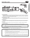
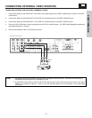
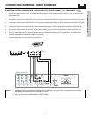
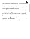
CONNECTING A COMPONENT SOURCE WITH DVI-HDTV CAPABILITY TO INPUT 1
1. Connect the DVI connection cable from the output of the HDTV set top box or DVD player to the DVI-HDTV input as shown on
the AVC Center below.
2. Connect the cable from the AUDIO OUT R of the HDTV set top box or DVD player to the INPUT (AUDIO/R) jack.
3. Connect the cable from the AUDIO OUT L of the HDTV set top box or DVD player to the INPUT (AUDIO/L) jack.
4. Press the VID1 button to view the program from the HDTV set top box or DVD player. The VIDEO OSD label disappears
automatically after approximately four seconds.
5. Press the ANT button to return to the previous channel.
NOTES: 1. Completely insert the connection cord plugs when connecting to rear panel jacks. The picture and sound that is
played back will be abnormal if the connection is loose.
2. The DVI-HDTV input on INPUT 1 contains the copy protection system called High-bandwidth Digital Content
Protection (HDCP). HDCP is a cryptographic system that encrypts video signals when using DVI connections to
prevent illegal copying of video contents.
3. DVI is not a “NETWORK” technology. It establishes a one-way point-to-point connection for delivery of
uncompressed video to a display.
4. The connected digital output device controls the DVI interface so proper set-up of device user settings determines
final video appearance.
P
B
P
R
P
B
P
R
P
B
P
R
TruBass SRS and symbol are trademarks of SRS Labs, Inc.
AC IN
TO MONITOR
Please use HITACHI specified cable.
Rear Panel of AVC Center
LR
OUTPUT
D-VHS
Y/VIDEO
R
L/(MONO)
AUDIO
L
R
S-VIDEO
VIDEO
AUDIO
R
S-VIDEO
VIDEO
AUDIO
R
S-VIDEO
VIDEO
MONITOR OUT INPUT 4 INPUT 3 IR BLASTER
L/(MONO)L/(MONO)
AUDIO
Y
R
L/(MONO)
AUDIO
INPUT 2 INPUT 1
ANT B
TO CONVERTER
ANT A
DIGITAL OUTPUT
DVI-HDTV
INPUT 1
L
AUDIO
R
AUDIO OUT
ANALOG INPUT
L/(MONO)
R
AUDIO
RGB
Back of
D-VHS