


18
First time use
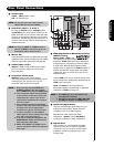
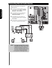
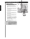
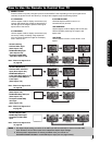
CONNECTING A COMPONENT
SOURCE TO INPUT 3 OR 4: Y-PBPR.
1. Connect the cable from the Y OUT of the
Laserdisc/DVD player or HDTV set top box to the
INPUT (Y) jack, as shown on the TV set on the
right.
2. Connect the cable from the C
B/PB OUT or B-Y OUT
of the Laserdisc/DVD player or HDTV set top box
to the INPUT (P
B) jack.
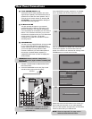
3. Connect the cable from the C
R/PR OUT or R-Y OUT
of the laserdisc/DVD player or HDTV set top box to
the INPUT (P
R) jack.
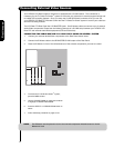
4. Connect the cable from the AUDIO OUT R of the
Laserdisc/DVD player or HDTV set top box to the
INPUT (AUDIO/R) jack.
5. Connect the cable from the AUDIO OUT L of the
Laserdisc/DVD player or HDTV set top box to the
INPUT (AUDIO/L) jack.
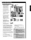
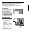
6. Press the the INPUTS button, then select INPUT 3
from the INPUTS menu to view the program from
the Laserdisc/DVD player or HDTV set top box. The
VIDEO OSD label disappears automatically after
approximately four seconds.
7. Select CABLE from the INPUTS menu to return to
the last channel tuned.
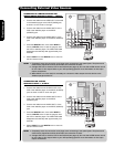
NOTE: 1. Completely insert the connection cord
plugs when connecting to rear panel jacks.
The picture and sound that is played back
will be abnormal if the connection is loose.
2. See page 13 for tips on REAR PANEL
CONNECTIONS.
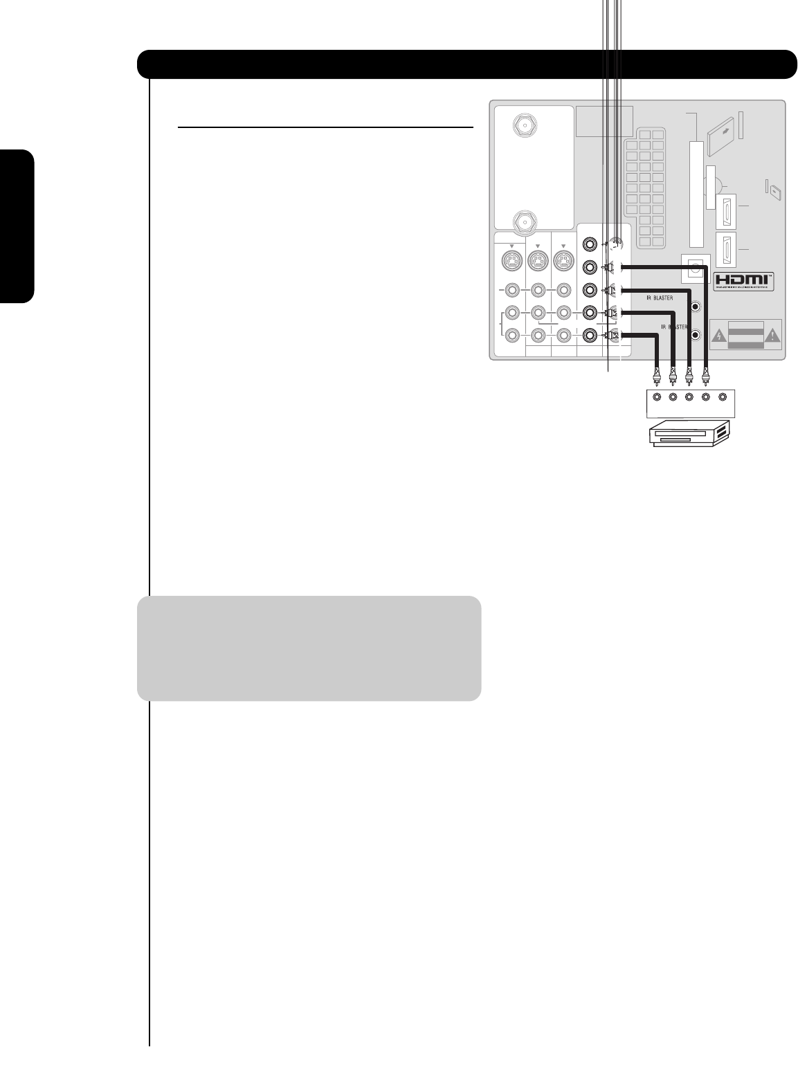
Connecting External Video Sources
R
L
A
U
D
I
O
V
I
D
E
O
S
I
V
I
D
E
O
(MONO)(MONO)(MONO)(MONO)
P
R
P
B
Y/
VIDEO
Y/
VIDEO
P
R
P
B
P
R
P
B
P
R
P
B
MONITOR OUT
AUDIO
TO HI-FI
INPUT 1
CABLE
AIR
INPUT 2
TV AS CENTER
INPUT 3 INPUT 4
CableCARD™
CAUTION
(Top of card faces right)
Top faces
OPTICAL OUT
Digital Audio
Upgrade Card
HDMI INPUT 1
Apparatus Claims of U.S.
Patent Nos. 4,631,603;
4,577,216; 4,819,098;
4,907,093; and 6,381,747
licensed for limited
viewing uses only.
DVD Player
PR PB YLR
G-LINK
/
OUTPUT
HDMI INPUT 2