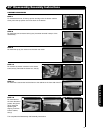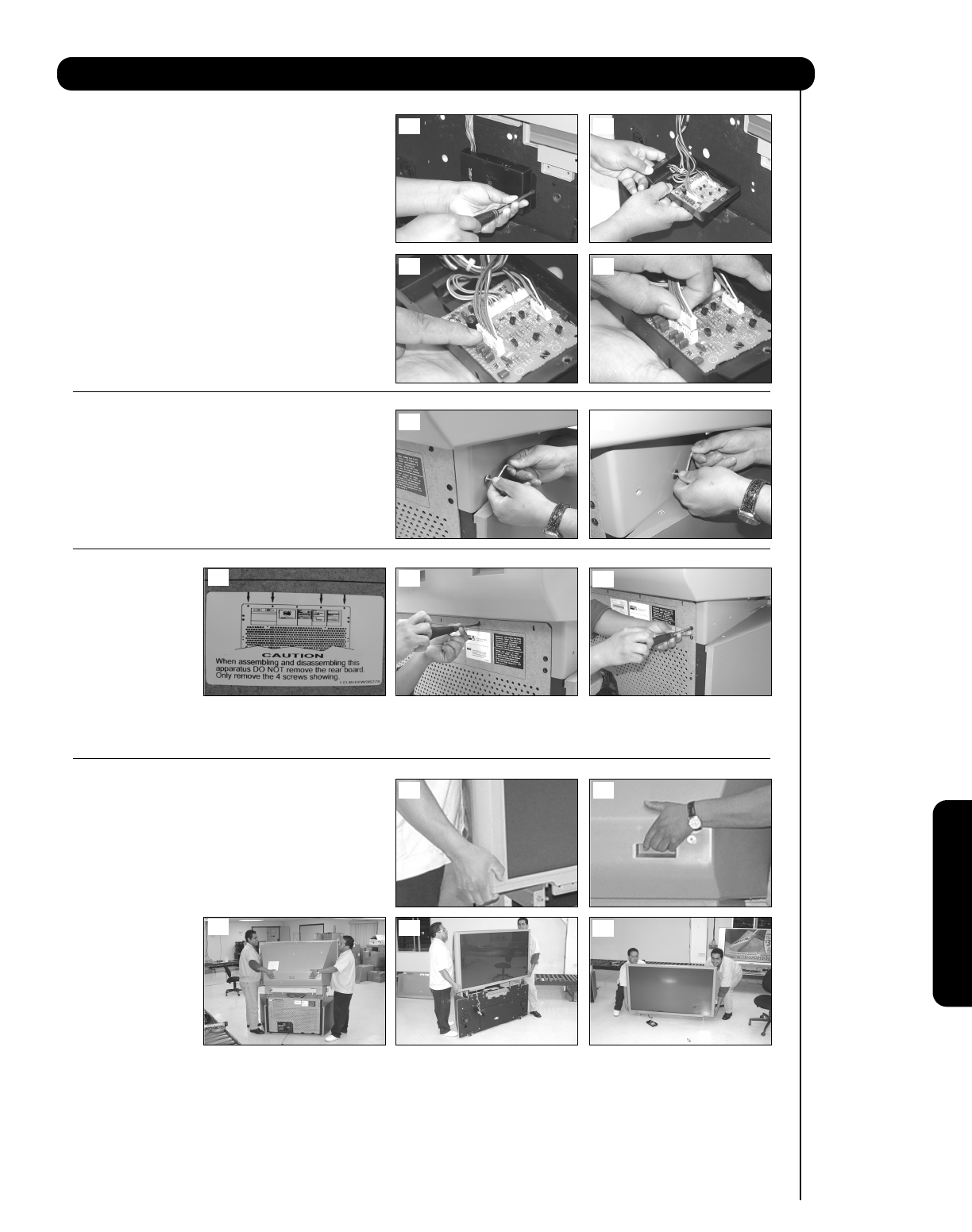
STEP 4
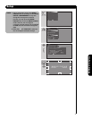
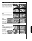
Remove the sensor box by unscrewing the 2 screws
located on both sides of the sensor box, see (a).
Rotate the sensor box and there are 4 low voltage
connectors located on the sensor board, see (b).
Disconnect the connector with the brown wires
(PDSE), see (c) and (d). (Make sure to push the
center lock on the connector at the unplug time.)
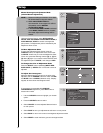
STEP 5
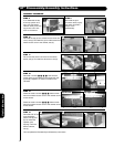
Remove the joint connector bolts from each side
of the back cover using the allen wrench that is
provided inside of the instruction bag, see (a)
and (b).
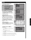
STEP 6
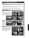
Remove from the
back side of the TV
set only the top 4
screws of the lower
rear cover, see (b),
as shown by the
arrows on the rear
cabinet label, see (a). Do not remove the rear cover board. Remove the (4) four side screws that hold the back
cover to the cabinet, see (c) as shown on the label (a). Total of 8 screws will be removed.
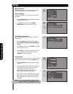
STEP 7
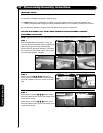
CAUTION: When the TV is separated, the top
portion weights 45 lbs. This task should be done by
two persons when separating this TV.
This assembly contains fragile parts, such as glass
and the viewing screen. Avoid any type of impact
that could cause breakage of these components.
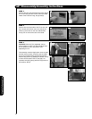
Remove top portion
by grabbing the
bottom corner of
frame and the back
cover, see (a)(b). Lift
upwards, see (c)(d),
gently place the top
portion on the the
floor, see (e).
57
57” Disassembly/Assembly Instructions
Useful Information
(a) (b)
(a)
(b)
(c)
(a) (b)
(c)
(d)
(e)
(a) (b)
(c) (d)


