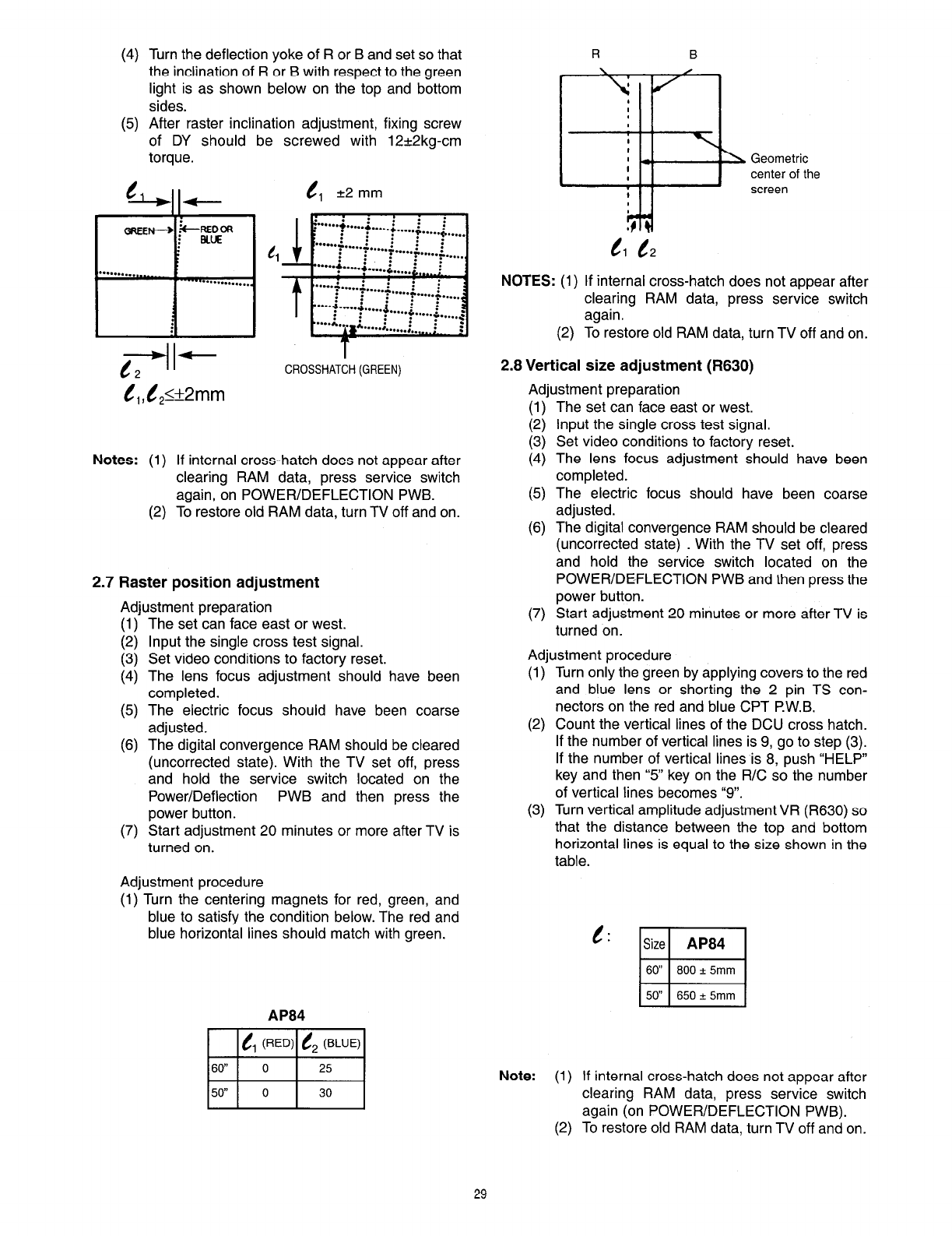
(4)
(5)
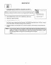
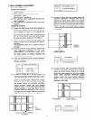
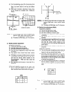
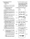
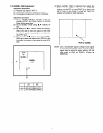
Turn the deflection yoke of R or B and set so that
the inclination of R or B with respect to the green
light is as shown below on the top and bottom
sides.
After raster inclination adjustment, fixing screw
of DY should be screwed with 12+2kg-cm
torque.
t?, +2
mm
iREDC34
n!yIIz
1 1 F”-f- . . . . f . . . . . f . . . . . i . . . . . i .... 1
t2 -
II
I
CROSSHATCH (GREEN)
Notes:
(1)
(2)
If internal cross-hatch does not appear after
clearing RAM data, press service switch
again, on POWER/DEFLECTION PWB.
To restore old RAM data, turn TV off and on.
2.7 Raster position adjustment
Adiustment oreparation
(1)
I:;
(4)
(5)
(6)
(7)
The set’can face east or west.
Input the single cross test signal.
Set video conditions to factory reset.
The lens focus adjustment should have been
completed.
The electric focus should have been coarse
adjusted.
The digital convergence RAM should be cleared
(uncorrected state). With the TV set off, press
and hold the service switch located on the
Power/Deflection PWB and then press the
power button.
Start adjustment 20 minutes or more after TV is
turned on.
Adjustment procedure
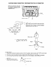
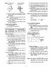
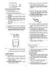
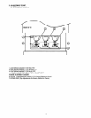
(1) Turn the centering magnets for red, green, and
blue to satisfy the condition below. The red and
blue horizontal lines should match with green.
twa4
Geometric
center of the
Cl
t2
NOTES:
(1) If internal cross-hatch does not appear after
clearing RAM data, press service switch
again.
(2) To restore old RAM data, turn TV off and on.
2.6 Vertical size adjustment (R630)
Adjustment preparation
I:;
(3)
(4)
(5)
(6)
(7)
The set can face east or west.
Input the single cross test signal.
Set video conditions to factory reset.
The lens focus adjustment should have been
completed.
The electric focus should have been coarse
adjusted.
The digital convergence RAM should be cleared
(uncorrected state) . With the TV set off, press
and hold the service switch located on the
POWER/DEFLECTION PWB and then press the
power button.
Start adjustment 20 minutes or more after TV is
turned on.
Adiustment procedure
(1)
(2)
(3)
Turn only the green by applying covers to the red
and blue lens or shorting the 2 pin TS con-
nectors on the red and blue CPT P.W.B.
Count the vertical lines of the DCU cross hatch.
If the number of vertical lines is 9, go to step (3).
If the number of vertical lines is 8, push “HELP”
key and then “5” key on the R/C so the number
of vertical lines becomes “9”.
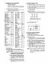
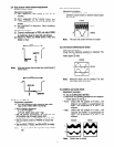
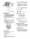
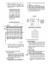
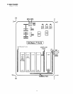
Turn vertical amplitude adjustment VR (R630) so
that the distance between the top and bottom
horizontal lines is equal to the size shown in the
table.
t:
Size
ma4
60” 8OOk
5mm
50” 65Ok
5mm
Note:
(1) If internal cross-hatch does not appear after
clearing RAM data, press service switch
again (on POWER/DEFLECTION PWB).
(2) To restore old RAM data, turn TV off and on.
29


