


TR21, TR22, TR23, AND TR24 WALL MODULES
62-0267—09 2
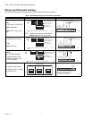
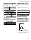
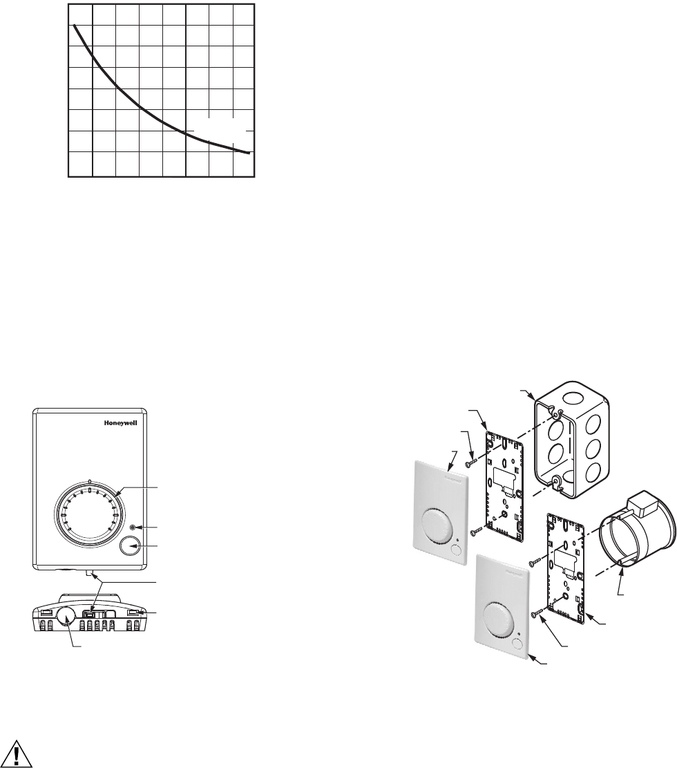
Fig. 1. Temperature vs. Resistance for Nonlinear Sensor.
Communications
All wall modules (except the TR21 and TR21-A models) have
a L
ONMARK
®
bus communications port. If needed, the jack
plug must be removed in the field, and terminals 3 and 4 wired
according to the installation instructions.
The recommended wire size for the LONMARK
®
bus is Level
IV, 22 AWG (0.34 sq.mm) plenum or non-plenum rated,
non-shielded, twisted pair, solid conductor wire.
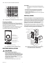
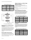
Fig. 2. Wall Module Features (TR23-F Shown).
BEFORE INSTALLATION
CAUTION
Erratic System Operation Hazard.
Failure to follow proper wiring practices can
introduce disruptive electrical interference (noise).
Keep wiring at least one foot away from large inductive
loads such as motors, line starters, lighting ballasts,
and large power distribution panels.
Shielded cable is required in installations where these
guidelines cannot be met.
Ground shield only to grounded controller case.
IMPORTANT
All wiring must comply with local electrical codes
and ordinances or as specified on installation wiring
diagrams.
— Wall module wiring can be sized from 16 to 22 AWG
(1.31 to 0.33 sq. mm) depending on the application.
— The maximum length of wire from a device to a wall
module is 1000 ft. (305 m).
— Twisted pair wire is recommended for wire runs longer than
100 ft. (30.5 m).
INSTALLATION
Mount the wall module on an inside wall approximately 54 in.
(1372 mm) from the floor (or in the specified location) to allow
exposure to the average zone temperature. Do not mount the
wall module on an outside wall, on a wall containing water
pipes, or near air ducts. Avoid locations that are exposed to
discharge air from registers or radiation from lights,
appliances, or the sun. See “Cover Disassembly” on page 3.
The wall module can be mounted on a wall, on a standard
utility conduit box using No. 6 (3.5 mm) screws or on a 60 mm
wall outlet box (see Fig. 3). When mounting directly on a wall,
use the type of screws appropriate for the wall material.
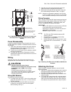
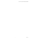
Fig. 3. Mounting on Standard Utility Conduit Box or
60 mm Wall Outlet Box (TR23 Shown).
TEMPERATURE (DEGREES)
o
F
30
40 50 60 70
80
90
100
110
0
10
20
30
40
RESISTANCE (OHMS)
20K OHM AT
77
o
F (25
o
C)
80K
70K
60K
50K
40K
30K
20K
10K
o
C
M5874A
M28125
FAN SWITCH, 3 OR 5 POSITION
DEPENDING ON MODEL
(TR22, TR23, AND TR24 MODELS ONLY)
LED (TR23 AND TR24 MODELS ONLY)
TEMPERATURE DIAL,
FAHRENHEIT DIAL SHOWN
(TR22 AND TR23 MODELS ONLY)
BYPASS (OVERRIDE) BUTTON
(TR23 AND TR24 MODELS ONLY)
LON CONNECTOR,
SHOWN WITH PROTECTIVE CAP IN PLACE
(NOT AVAILABLE ON TR21 AND TR21-A MODELS)
LOCKING TAB SLOT (X2)
60
70
80
M28126
STANDARD UTILITY CONDUIT BOX
SUBBASE
NO. 6 SCREW
60 mm WALL
OUTLET BOX
SUBBASE
3.5 mm SCREW
FRONT COVER
FRONT COVER