


TR21, TR22, TR23, AND TR24 WALL MODULES
62-0267—09 6
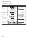
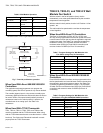
Fig. 7. Override pushbutton operation.
When Used With Excel 600/500/100/80/50
Controllers:
The application engineer/programmer can program the
override (bypass) and LED to operate in any manner desired.
The override (bypass) input is a dry contact, normally open,
momentary digital input when the wall module does not have a
fan switch. When a fan speed switch (basically a series of
resistances based on fan switch position) is present, the
override button is an analog input. See Table 4 for
resistances.
When Used With T7350 Thermostat:
TR21, TR21-A, TR21-H, TR22, TR23, and TR24 are the
models compatible with the T7350 thermostat. When using
with the T7350 thermostat be sure to use the relative +/- offset
knob only. The Celsius and Fahrenheit knobs will not work
properly with the T7350 Thermostat.
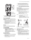
TR22-F5, TR23-F3, and TR23-F5 Wall
Module Fan Switch
With the switch in the far left position (Auto), the fan
automatically runs at the speed determined by the controller
temperature control algorithm.
With the switch in the 0 position, the fan is off. Position 1 is fan
speed 1, etc.
The wall module fan speed switch overrides the temperature
control algorithm.
When Used With Excel 10 Controllers:
The Excel 10 Controllers (W7750, W7751, W7752, and
W7753) can be programmed so that the fan speed switch and
override button function the way that the application engineer/
programmer wants. See Table 7 for controller-programming
resistances. Switch 1 on Dip Switch S2 adds 10k Ohms
resistance when OPEN (for Excel 600-80 controllers) and
removes it when CLOSED (for Excel 10 controllers).
When Used With Excel 600/500/100/80/50
Controllers:
Excel 600/500/100/80 Controllers can be programmed so that
the fan speed switch and override button function the way that
the application engineer/programmer wants. See Table 8 for
controller-programming resistances. Switch 1 on Dip Switch
S2 adds 10k Ohms resistance when OPEN (for Excel 600-80
controllers) and removes it when CLOSED (for Excel 10
controllers).
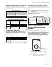
Table 6. Wall Module Operation.
Pushbutton Held Down Controller Model LED Status
0 to 1 second No override Off
1 to 4 seconds Timed occupied
override
On
4 to 7 seconds Unoccupied override Single blink per second
Longer than 7 seconds No override Off
not applicable Continuous occupied
override
a
a
Remote function, which is generated from the network.
Two blinks per second
OVERRIDE
OCCUPIED
(LED ON)
UNOCCUPIED
(LED BLINK)
NOT ASSIGNED
(LED OFF)
RESET
M28145
PRESS FOR ONE
TO FOUR SECONDS
PRESS FOR FOUR
TO SEVEN SECONDS
PRESS FOR
LESS THAN
ONE SECOND
PRESS FOR
LESS THAN
ONE SECOND
PRESS FOR
MORE THAN
SEVEN SECONDS
BYPASS
TIMEOUT
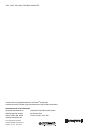
Table 7. Program Settings for Wall Modules with
Fan Switch using Excel 10 Controllers.
For Switch Position Resistance (Ohms) Comment
Auto 1861 ±119 Left most position
0 2686 ±127 Fan Off position
1 3866 ±139
2 3041 ±130
3 4601 ±146 Right most position
Override button closed Closed circuit
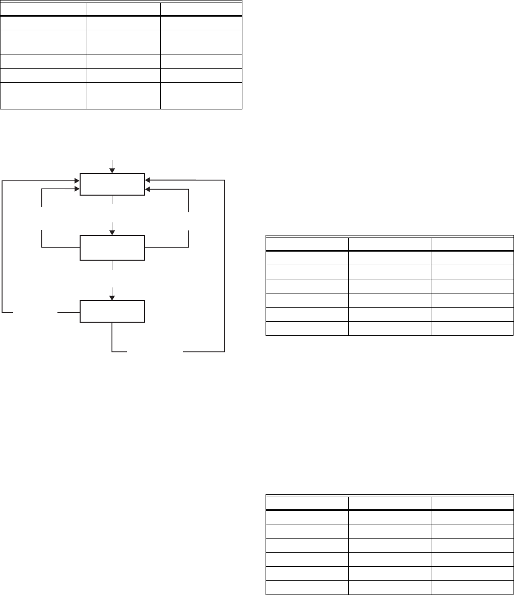
Table 8. Program Settings for Wall Modules with
Fan Switch using Excel 600/500/100/80 Controllers.
For Switch Position Resistance (Ohms) Comment
Auto 11.861K ±119 Left most position
0 12.686K ±127 Fan Off position
1 13.866K ±139
2 13.04K ±130
3 14.60K ±146 Right most position
Override button closed 10K ±100