


TR21, TR22, TR23, AND TR24 WALL MODULES
3 62-0267—09
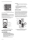
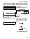
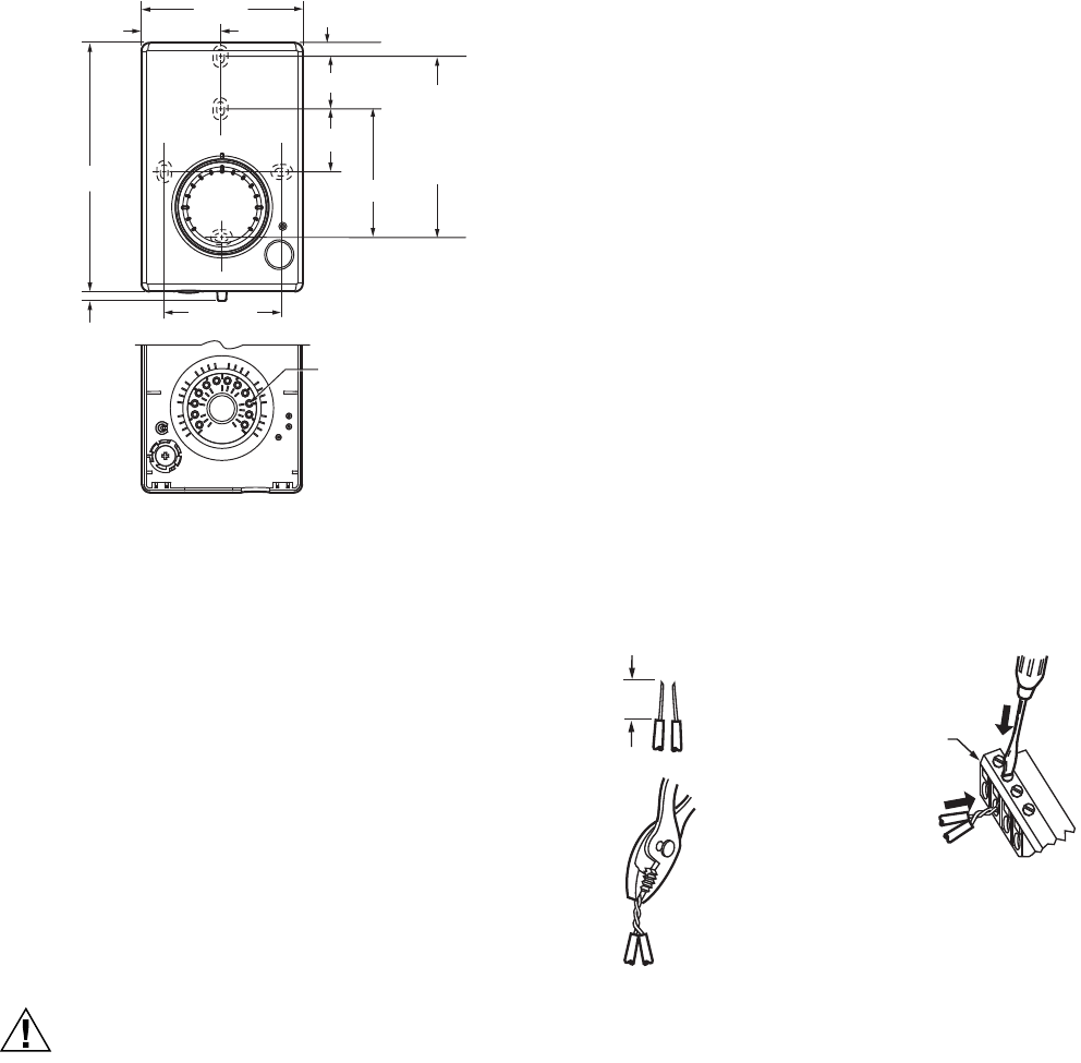
Fig. 4. Wall Module Subbase Dimensions in Inches (mm)
and Temperature Limit Set Screw Locations (TR23
Shown).
Cover Disassembly
A snap-fit locking mechanism is used to attach the cover of
the wall module to its subbase. To disassemble the cover from
the subbase:
1. Insert a thin, flat blade screwdriver into each of the two
slots at the bottom of the module to release the two
locking tabs. See Fig. 2 on page 2.
2. Tilt the cover out and away from the subbase to release
the top two locking tabs.
3. To change the dial (e.g. from Fahrenheit to Celsius)
release the two tabs on the inside of the front cover and
remove the old dial.
Wiring
Attach the wires from the device sensor terminals to the
appropriate wall module terminals. See Table 1 on page 4.
CAUTION
Improper Electrical Contact Hazard.
Screw type terminal blocks are designed to accept
no more than one 16 AWG (1.31 sq. mm)
conductor.
Connect multiple wires that are 16-18 AWG
(1.31-0.82 sq. mm) with a wire nut. Include a pigtail
with this wire group and attach the pigtail to the
individual terminal block.
Wiring Wall Modules
Wire the terminal block as follows:
1. For single wires, strip 3/16 in. (5 mm); for multiple wires
going into one terminal, strip 1/2 in. (13 mm) insulation
from the conductor.
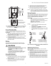
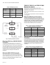
2. If two or more wires (20 to 22 AWG only) are being
inserted into one terminal, twist the wires together
before inserting. See Fig. 5.
3. Insert the wire in the required terminal location and
tighten the screw to complete the termination.
4. Review and verify the terminal connection wiring and
DIP switch settings illustrated in Table 1 on page 4.
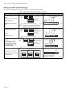
NOTE: Wire the Lon connection (terminals 3 and 4) using
Level IV 22 AWG (0.34 mm
2
) plenum or non-plenum
rated, unshielded, twisted pair, solid conductor wire.
Wiring Examples
Table 1 on page 4 illustrates DIP switch settings and terminal
connections for the wall modules. Refer to the TR21, TR22,
TR23, and TR24 Wall Modules – Specification Data, form
63-1321, for additional DIP Switch information.
IMPORTANT
SW 2 on DIP Switch S2 is used for factory calibration
of the temperature setpoint potentiometer.
Depending on calibration, this switch may be set in
either the On or Off position.
DO NOT change the position of this switch.
NOTES:
1. The TR21 and TR22 models do not use DIP
Switch S1 and S3.
2. DIP Switch S1 is used only on the humidity
models, TR21-H and TR23-H.
3. Models TR21 and TR21-A use terminals 1 and 2
only. Model TR21-J uses terminals 1, 2, 3, and 4
only.
Fig. 5. Attaching Two Wires (20 to 22 AWG) to Wall Module
Terminals.
Attaching the Cover
When all wiring is complete, attach the cover of the Wall
Module as follows:
1. Optional: For models with a temperature dial, insert the
two setpoint screws into the inside of the cover to set
the desired temperature range limit. See Fig. 4.
2. Press the cover straight down onto the subbase until it
snaps into place.
3. For models with a temperature dial, insert the desired
dial through the opening in the cover. Align the keyed
shaft on the knob with the keyed slot into the fitting on
the subbase, then press down until it snaps into place.
70
55
60
65
70
75
80
85
15
20
25
°F
°C
+
–
M25482
2 1/4 (57)
3/16 (5)
1 3/16 (31)
STANDARD
UTILITY
CONDUIT
BOX (2 X 4)
MOUNTING
HOLES
60
80
INSIDE OF
FRONT
COVER
TEMPERATURE LIMIT
SCREW POSITION (X12)
NOTE: IF DESIRED, INSERT THE
TWO SETPOINT SCREWS INTO
THE DESIRED POSITIONS.
2 3/8 (60)
9/16 (14)
4 13/16 (122)
3 (76)
1 1/2 (38)
7/8 (22)
1/2
(13)
STRIP 1/2 IN.
(13 MM) FROM
WIRES TO BE
ATTACHED AT
ONE TERMINAL.
1.
2.
TWIST WIRES
TOGETHER
WITH PLIERS
(A MINIMUM OF
THREE TURNS).
3.
CUT TWISTED END OF WIRES TO
3/16 IN. (5 MM) BEFORE INSERTING
INTO TERMINAL AND TIGHTENING
SCREW. THEN PULL ON EACH WIRE
IN ALL TERMINALS TO CHECK FOR
GOOD MECHANICAL CONNECTION.
M11413
CONTROLLER OR
WALL MODULE
E-BUS CONNECTOR
TERMINALS