


17
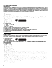
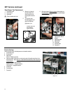
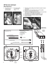
CPU Module Replacement
The CPU Module (Central Processing Unit) and the Power Module are not field
repairable, they must be returned to IDEAL for service.
The CPU is located behind the faceplate on the inside of front lid.
1. Disconnect power.
2. Disconnect air.
3. Open front lid all the way so that it rests on top of rear cover.
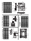
4. Remove the six #8-32 button head screws from faceplate.
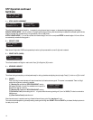
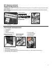
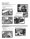
Power Module Replacement
The Power Module is attached to the top of rear cover.
1. Disconnect power.
2. Disconnect air.
3. Remove the five #8-32 button head screws from the rear panel
and remove rear panel.
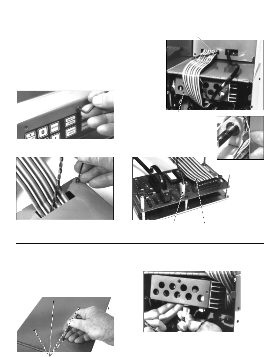
4. Open lid and support Power Module while removing the four
#6-32 button head screws from top of rear cover.
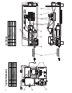
5. Slide ribbon cable to side and remove module while disconnect-
ing the five plug-in electrical connections
6. Return entire module to IDEAL for service.
7. Reverse process to replace module.
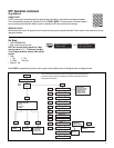
TWO WIRE CABLE RIBBON CABLE
REMOVE 4 SCREWS
5. Lay module flat and remove the four screws from the
back of the CPU and lift cover off.
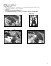
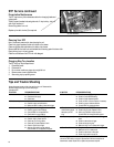
7. Replace cover and return entire module to IDEAL for
service.
8. Reverse process to replace module.
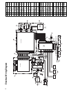
6. Disconnect ribbon cable, 2 wire cable and
pull wires out of cover.
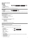
NOTE: When closing the lid, make sure
all wires and air hoses do not interfere.
CPU MODULE
POWER MODULE
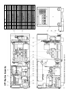
STP Service continued