


30
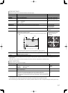
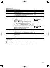
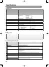
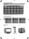
Dimensions Unit: mm (inch)
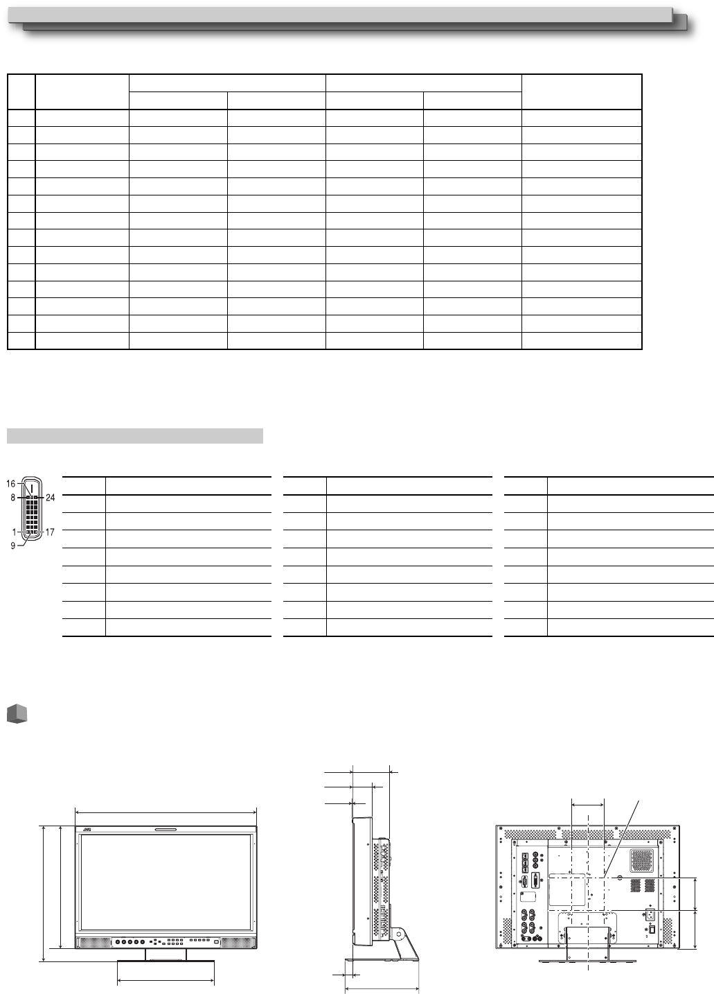
<Front view> <Side view> <Rear view>
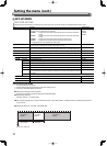
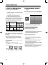
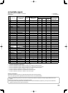
Computer signals (preset)
DVI-D (HDCP) terminals
No. Signal name
Resolution Frequency
Scan system
Horizontal Vertical Horizontal (kHz) Vertical (Hz)
1 VGA60 640 480 31.5 59.9 Non-interlace
2 WVGA60 852 480 31.5 59.9 Non-interlace
3 SVGA60 800 600 37.9 60.3 Non-interlace
4 XGA60 1024 768 48.4 60.0 Non-interlace
5 WXGA (1280) 1280 768 47.8 60.0 Non-interlace
6 WXGA+60 1440 900 55.9 60.0 Non-interlace
7 SXGA60 1280 1024 64.0 60.0 Non-interlace
8 WSXGA+60 1680 1050 65.2 60.0 Non-interlace
9 UXGA60 *
1
1600 1200 75.0 60.0 Non-interlace
10 WUXGA60 *
1
1920 1200 74.0 60.0 Non-interlace
11 720/60p 1280 720 45.0 60.0 Non-interlace
12 1080/60p 1920 1080 67.5 60.0 Non-interlace
13 720/50p 1280 720 37.5 50.0 Non-interlace
14 1080/50p 1920 1080 56.25 50.0 Non-interlace
*
1
In 1:1 mode, the top and bottom of the screen will be hidden.
● Even for a preset signal, picture may not be normally displayed depending on the signal timing.
● When a preset signal comes in, the signal format is shown on the status display. For other signals, the resolution is shown.
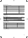
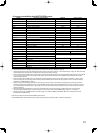
Specification of the DVI-D (HDCP) terminal
Connect it to the DVI-D output terminal on a personal computer.
Pin No.
Input signal
1 T.M.D.S Data 2–
2 T.M.D.S Data 2+
3 T.M.D.S Data 2 shield
4 NC
5 NC
6 DDC Clock
7 DDC Data
8 NC
Pin No.
Input signal
9 T.M.D.S Data 1–
10 T.M.D.S Data 1+
11 T.M.D.S Data 1 shield
12 NC
13 NC
14 +5 V Power
15 GND
16 Hot Plug Detect
Pin No.
Input signal
17 T.M.D.S Data 0–
18 T.M.D.S Data 0+
19 T.M.D.S Data 0 shield
20 NC
21 NC
22 T.M.D.S Clock shield
23 T.M.D.S Clock+
24 T.M.D.S Clock–
347 (13 3/4˝)
387.8 (15 3/8˝) (High)/
352.5 (14˝) (Low)
515 (20 3/8˝)
240 (9 1/2˝)
199 (7 7/8˝)
53 (2 1/8˝)
99.8 (4˝)
1.3 (1/16˝)
20 (7/8˝)
VESA mounting holes
(Size: 4-M4, depth: 10 mm)
100
100
115 (4 5/8˝)
Specifications (cont.)